Measuring and Test Circuit
20_VDC_FET_VOLTMETER
Published:2009/7/15 2:07:00 Author:Jessie | From:SeekIC

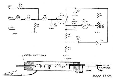
Has high input impedance as required for accurate measurements in solid-state circuit, Uses Motorola MPF102, HEP802, or equivalent N-channel JFET. If meter cannot be zeroed, change R7 to 10,000 ohms for greater zeroing range. 2-V range gives extra flexibility. Half-wave RF probe using 1N914 or equivalent high-speed switching diode responds to peak RF voltage being measured. R11 reduces peak value to RMS value. Connect probe to known 10-VRMS source, then adjust R11 so meter reads 10 V.-D, DeMaw and L. McCoy, Learning to Work with Semiconductors, QST, April 1974, p 20-25 and 41.
Reprinted Url Of This Article:
http://www.seekic.com/circuit_diagram/Measuring_and_Test_Circuit/20_VDC_FET_VOLTMETER.html
Print this Page | Comments | Reading(3)

Article Categories
power supply circuit
Amplifier Circuit
Basic Circuit
LED and Light Circuit
Sensor Circuit
Signal Processing
Electrical Equipment Circuit
Control Circuit
Remote Control Circuit
A/D-D/A Converter Circuit
Audio Circuit
Measuring and Test Circuit
Communication Circuit
Computer-Related Circuit
555 Circuit
Automotive Circuit
Repairing Circuit
Code: