Measuring and Test Circuit
1_kW_POWER_METER
Published:2009/6/18 23:40:00 Author:May | From:SeekIC

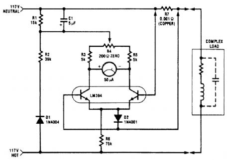
The power meter shown uses only one transistor pair to provide the complete (X)(Y)function.The circuit is intended for 117 Vac±50 Vac operation, but can be easily modified for higher or lower voltages. It measures true (nonreactive)power being delivered to the load and requires no external power supply. Idling power drain is only 0.5W. The load current-sensing voltage is only 10 mV, keep-ing load voltage loss to 0.01%. Rejection of reactive load currents is better than 100:1 for linear loads.Nonlinearity is about 1% full scale when using a 50-μA meter movement. The temperature correction for gain is accomplished by using a copper shunt (+0.32%/℃) for load-current sensing. This circuit measures power on negative cycles only, so it cannot be used on rectifying loads.
Reprinted Url Of This Article:
http://www.seekic.com/circuit_diagram/Measuring_and_Test_Circuit/1_kW_POWER_METER.html
Print this Page | Comments | Reading(3)

Article Categories
power supply circuit
Amplifier Circuit
Basic Circuit
LED and Light Circuit
Sensor Circuit
Signal Processing
Electrical Equipment Circuit
Control Circuit
Remote Control Circuit
A/D-D/A Converter Circuit
Audio Circuit
Measuring and Test Circuit
Communication Circuit
Computer-Related Circuit
555 Circuit
Automotive Circuit
Repairing Circuit
Code: