LED and Light Circuit
_EIGHT_OHANNEL_VOLTAGE_DISPLAY
Published:2009/7/9 1:57:00 Author:May | From:SeekIC
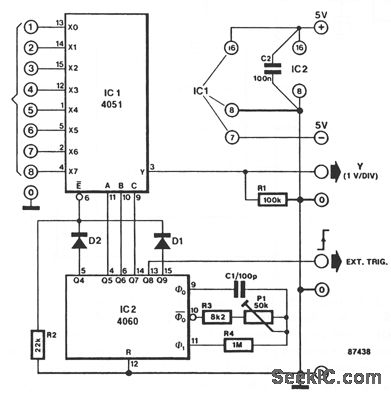
This circuit turns a common oscilloscope into a versatile eight-channel display for direct voltages. The trend of each of the eight input levels is readily observed, albeit that the attainable resolution is not very high.
The circuit diagram shows the use of an eight-channel analog multiplexer IC1, which is the electronic version of an eight-way rotary switch with contacts X0 through X7 and pole Y. The relevant channel is selected by applying a binary code to the A-B-C inputs. For example, binary code 011 (A-B-C) enables channel 7 ( X6 Y ). The A-B-C inputs of IC1 are driven from three successive outputs of binary counter IC2, which is set to oscillate at about 50 kHz with the aid of P1. Since the counter is not reset, the binary state of outputs Q5, Q6, and Q7 steps from 0 to 7 in a cyclic manner. Each of the direct voltages at input terminals 1 to 8 is therefore briefly connected to the Y input of the oscilloscope. All eight input levels can be seen simultaneously by setting the timebase of the scope, in accordance with the time it takes the counter to output states 0 through 7, on outputs Q5, Q6, and Q7.
The timebase on the scope should be set to 0.5 ms/div, and triggering should occur on the positive edge of the external signal. Set the vertical sensitivity to 1 V/div. The input range of this circuit is from -4 V to +4 V; connected channels are terminated in about 100 KΩ.
Reprinted Url Of This Article:
http://www.seekic.com/circuit_diagram/LED_and_Light_Circuit/_EIGHT_OHANNEL_VOLTAGE_DISPLAY.html
Print this Page | Comments | Reading(3)

Article Categories
power supply circuit
Amplifier Circuit
Basic Circuit
LED and Light Circuit
Sensor Circuit
Signal Processing
Electrical Equipment Circuit
Control Circuit
Remote Control Circuit
A/D-D/A Converter Circuit
Audio Circuit
Measuring and Test Circuit
Communication Circuit
Computer-Related Circuit
555 Circuit
Automotive Circuit
Repairing Circuit
Code: