LED and Light Circuit
Voice controlling music lantern circuit (3)
Published:2012/12/18 2:01:00 Author:Ecco | Keyword: Voice controlling , music lantern | From:SeekIC

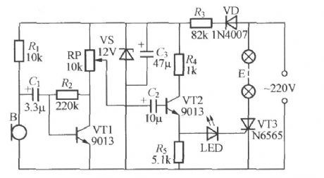
Transistor VT3 forms a main circuit of the lantern E, VT1 and VT2 form a control loop, the 220V AC is rectified by VD, Buck by R3, regulated by VS and filtered by C3 filter to output about 12V stable DC voltage for controlling the loop's power. Microphone B can pick up acoustic signal of indoor environment, then it convert it to electric signal which is amplified by the transistor VT1 level, then the amplified signal is flowing to the base of VT2 ( RP is a voice sensitivity adjustment potentiometer) by RP and C2. VT2 is connected into a non - biased emitter follower.
Reprinted Url Of This Article:
http://www.seekic.com/circuit_diagram/LED_and_Light_Circuit/Voice_controlling_music_lantern_circuit_3.html
Print this Page | Comments | Reading(3)

Article Categories
power supply circuit
Amplifier Circuit
Basic Circuit
LED and Light Circuit
Sensor Circuit
Signal Processing
Electrical Equipment Circuit
Control Circuit
Remote Control Circuit
A/D-D/A Converter Circuit
Audio Circuit
Measuring and Test Circuit
Communication Circuit
Computer-Related Circuit
555 Circuit
Automotive Circuit
Repairing Circuit
Code: