LED and Light Circuit
Triple Stroboscope
Published:2013/7/22 20:14:00 Author:muriel | Keyword: Triple Stroboscope | From:SeekIC

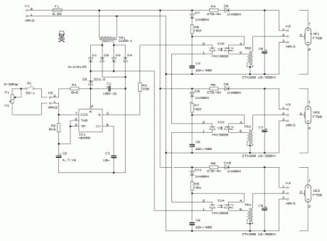
This circuit enables observation of movement between other stroboscopes. Generation of rectangular signal is based on NE555. This circuit requires a low power supply that is made from a simple transformer TR1, traditional rectifier bridge and zener diode.NE555 works in multivibrator mode generating astable pulses of 2Hz to 20Hz.The frequency is adjusted by potentiometer P1. The control potentiometer P1 can be placed as far as 30 meters away, for suspension of stroboscope’s work from far away.It is east to find all parts with facility in every electronic store, but it may be difficult to find the transformers TR2, TR3, TR4.Take extreme care handling this circuit because near C5-C7-C9 high voltages are present.
PartsR1 = 6,8 kR2 = 5,6 kR3 = 330R4,R6,R8 = 270 / 5 WR5,R7,R9 = 220 kP1 = 100 k linear potentiometerC1 = 100 uF / 16 VC2 = 4,7 uF / 16 VC3 = 10 nFC4,C6,C8 = 22 nF / 400 V, MKSC5,C7,C9 = 10 uF / 350 V, electrolytic (high quality)TR1 = Ordinary transformer 230 V / 9 V, 1,5 VATR2,TR3,TR4 = stroboscope transformer np (ZTK200)D1,D2,D3,D4 = 1N4149D5 = BZX85V Zener 3.9D6,D7,D8,D9,D10,D11 = 1N4004IO1 = NE555IO2,IO3,IO4 = MOC3020XE1,XE2,XE3 = stroboscope lamps FT50F1 = Fuse 0.8 A, 20 mmK1,K5 = connectors ARK200-2K2,K3,K4 = connectors ARK200-3S1 = Switch
Reprinted Url Of This Article:
http://www.seekic.com/circuit_diagram/LED_and_Light_Circuit/Triple_Stroboscope.html
Print this Page | Comments | Reading(3)

Article Categories
power supply circuit
Amplifier Circuit
Basic Circuit
LED and Light Circuit
Sensor Circuit
Signal Processing
Electrical Equipment Circuit
Control Circuit
Remote Control Circuit
A/D-D/A Converter Circuit
Audio Circuit
Measuring and Test Circuit
Communication Circuit
Computer-Related Circuit
555 Circuit
Automotive Circuit
Repairing Circuit
Code: