© 2008-2012 SeekIC.com Corp.All Rights Reserved.
LED and Light Circuit
MODEL_ROCKET_IGNITION_CIRCUIT
Published:2009/7/13 22:10:00 Author:May | From:SeekIC

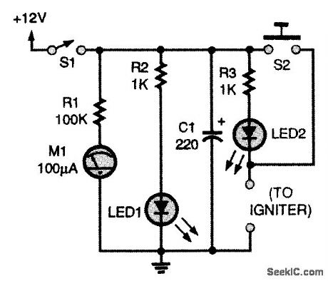
This circuit requires a 12-Vdc source. A battery pack of eight AA cells in series will work. Meter M1 gives you an indication of battery voltage; change the batteries when you see a noticeable drop in current. The circuit contains two LEDs: LED1 reminds you that the circuit is powered up, and LED2 lets you know that you have continuity through the igniter and are ready to fly. Capacitor C1 gives igniters that extra kick they occasionally need. Pushing the momentary push-button switch (S2) sends the rocket on its way. Use a red switch for that. The igniter leads are connected to the plugs marked igniter.
Reprinted Url Of This Article:
http://www.seekic.com/circuit_diagram/LED_and_Light_Circuit/MODEL_ROCKET_IGNITION_CIRCUIT.html
Print this Page | Comments | Reading(3)

Article Categories
power supply circuit
Amplifier Circuit
Basic Circuit
LED and Light Circuit
Sensor Circuit
Signal Processing
Electrical Equipment Circuit
Control Circuit
Remote Control Circuit
A/D-D/A Converter Circuit
Audio Circuit
Measuring and Test Circuit
Communication Circuit
Computer-Related Circuit
555 Circuit
Automotive Circuit
Repairing Circuit
New published articles
Response in 12 hours

Code: