LED and Light Circuit
Light Activated Siren Circuit
Published:2013/10/24 20:10:00 Author:lynne | Keyword: Light Activated Siren Circuit | From:SeekIC

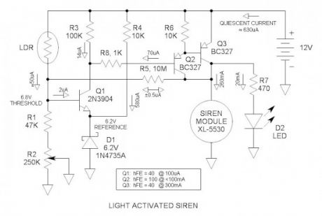
This light activated siren could make an unknowing “victim” wet his pants when turning on the lights in a dark room. This thing is LOUD! Power into the module is 3W and produces a 123db sound level from its 50mm diameter diaphragm. It wavers between 2kHZ and 4kHZ. An LDR senses ambient light level and switches on the power to the siren module via a transistor comparator and a darlington driver.The threshold is adjustable.
Schematic of the light activated siren
Input divider
The LDR and R1 & R2 form a voltage divider whose output voltage is light dependent. As the light level increases, the junction of the LDR and R1 increases. When it reaches 6.8V, Q1 turns on and subsequently triggers the alarm. Pot R2 calibrates the divider for the required light level threshold. The voltage out of the divider may be measured with a voltmeter so you can see what is happening as you debug the circuit.
Transistor comparator
Q1 is an NPN transistor applied as a comparator. Never heard of a transistor comparator before—well now you have—not exactly high performance with limited gain and 600mV offset, but fully functional and perfect for this application. Q1 has a minimum current gain (hFE) of 40 at low current levels. When the LDR is fully off, the Vbe of Q1 is -6.2V. Most transistors are rated for 6 to 7V reverse bias on the base to emitter junction.
Voltage reference
D1 is a 6.2V zener diode that is used as a voltage reference. R4 provides the required bias current. The cathode of the zener is a low impedance node for the emitter of Q1 to work into.
Darlington driver
Q2 & 3 are discrete high current TO-92 PNP transistors wired in the darlington configuration. In this configuration, the hFE is essentially squared so that it provides adequate current gain to easily drive the 280mA load.
Positive feedback
R5 provides about 1% positive feedback to insure positive switching as soon as the threshold is exceeded. This is also called hysteresis. R5 may be adjusted for best performance.
Circuit not tested
Generally the circuits I submit to electroschematics.com have been built and tested. This one has not, but I have a high level of confidence that it will work OK. It simulates fine in my cranial simulator.
Circuit operation
When light falls on the LDR, its resistance decreases and the voltage at the junction of the LDR and R1 increases. When the voltage exceeds 6.8V, Q1 turns on. The collector current of Q1 is the base current of the darlington driver and turns it on. This is called a high-side driver because it works against the positive bus. When voltage appears across the siren module, the voltage across and current through R5 reverses polarity and forces the voltage at the input voltage divider slightly higher thus causing it to “snap” on positively. When three transistors are wired like this, the DC gain is so high that a minute amount of leakage can cause circuit malfunction. R3 and R6 provide paths for leakage current thus insuring reliable operation.
For the future
Temperature activated siren circuit—actually you can do this now by simply replacing the LDR with an NTC thremistor.
Undocumented words and idioms (for our ESL friends)
debug—troubleshooting term. Literally, to get the insects out. From the early days of relay based computers where a moth took down a system when its wings got into the contacts of a relay.
Reprinted Url Of This Article:
http://www.seekic.com/circuit_diagram/LED_and_Light_Circuit/Light_Activated_Siren_Circuit.html
Print this Page | Comments | Reading(3)

Article Categories
power supply circuit
Amplifier Circuit
Basic Circuit
LED and Light Circuit
Sensor Circuit
Signal Processing
Electrical Equipment Circuit
Control Circuit
Remote Control Circuit
A/D-D/A Converter Circuit
Audio Circuit
Measuring and Test Circuit
Communication Circuit
Computer-Related Circuit
555 Circuit
Automotive Circuit
Repairing Circuit
Code: