LED and Light Circuit
LED Optocoupler circuit
Published:2012/10/9 2:36:00 Author:muriel | Keyword: LED Optocoupler | From:SeekIC


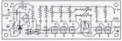
This LED Optocoupler circuit uses two ordinary LEDs as the optocoupler element. When a voltage of 2V is fed to the input, LED 2 will generate a voltage that is strong enough to switch on transistor T5. The upper frequency limit is around 38 kHz. Very low pulse frequencies are almost meaningless for the circuit.Eventhough the LEDs are quite intensive to stray light, it is a good idea to enclose them with an opaque box. Resistor R2 must be selected basing on the power supply voltage. It can be between 680 Ω and 1 KΩ. Resistor R11 must not be lower than 220 Ω.Transistor T6 has an open-collecter character.
Optocoupler Circuit Diagram
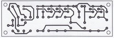
Optocoupler PCB and Parts Placement
Reprinted Url Of This Article:
http://www.seekic.com/circuit_diagram/LED_and_Light_Circuit/LED_Optocoupler_circuit.html
Print this Page | Comments | Reading(3)

Article Categories
power supply circuit
Amplifier Circuit
Basic Circuit
LED and Light Circuit
Sensor Circuit
Signal Processing
Electrical Equipment Circuit
Control Circuit
Remote Control Circuit
A/D-D/A Converter Circuit
Audio Circuit
Measuring and Test Circuit
Communication Circuit
Computer-Related Circuit
555 Circuit
Automotive Circuit
Repairing Circuit
Code: