LED and Light Circuit
Electronic Doorbell Light Schematic
Published:2012/9/24 4:23:00 Author:muriel | Keyword: Electronic, Doorbell, Light | From:SeekIC

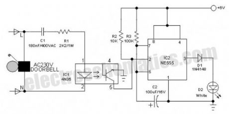
This 6V battery operated doorbell light circuit can be connected in parallel with any existing AC230V doorbell. When anyone push the doorbell switch, the bell sounds as usual and ac mains supply available across the doorbell is routed to the input of this circuit through an opto-coupler(IC1).Conduction of IC1 triggers a monostable, wired around the good old 555 timer (IC2). As a result the high-bright white LED (D2) at the output of IC2 is switched on for a short time. This circuit is highly useful at night/midnight as it gives sufficient indoor light to help you locate switches for room lamp/porch light, etc. On/Off duration of the LED light can be increased/decreased by increasing/decreasing the value of C2.The electronic doorbell light circuit is fully safe because it is perfectly isolated from the fatal ac mains supply by IC1. However, keep to avoid accidental contacts with the front end of the circuit, which is directly connected to the ac supply. Use of a good and convenient ABS enclosure is recommended for this doorbell light unit.
Electronic Doorbell Light Circuit Schematic
?
12 Responses to “Electronic Doorbell Light Schematic”
Reprinted Url Of This Article:
http://www.seekic.com/circuit_diagram/LED_and_Light_Circuit/Electronic_Doorbell_Light_Schematic.html
Print this Page | Comments | Reading(3)

Article Categories
power supply circuit
Amplifier Circuit
Basic Circuit
LED and Light Circuit
Sensor Circuit
Signal Processing
Electrical Equipment Circuit
Control Circuit
Remote Control Circuit
A/D-D/A Converter Circuit
Audio Circuit
Measuring and Test Circuit
Communication Circuit
Computer-Related Circuit
555 Circuit
Automotive Circuit
Repairing Circuit
Code: