LED and Light Circuit
DUAL_TRACE_CONVERTER
Published:2009/7/20 4:15:00 Author:Jessie | From:SeekIC

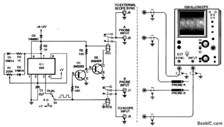
The probe switching circuit is shown in the figure. Two SPST reed relays, RY1 and RY2, switch the signal from two probes to a single scope input. Reed relays provide smooth and noise-free switching. The input side of each relay is connected to a scope probe, and the outputs of the relays are tied together and connected to the scope's single-channel input. A 555 timer, IC1, is con-figured as a variable-duty-cycle square-wave oscillator. Potentiometer R1 varies the oscillator's duty cycle to compensate for response-time variations that different relays might have. The potentiometer is adjusted to give equal brightness to both of the signals being displayed on the oscilloscope. If the relays you choose work well with a 50-percent duty cycle, the potentiometer can be replaced with two fixed resistors wired in series, with the junction between the two resistors connected to pin 2 of IC1. With the parts values shown, the timer has an output frequency of about 80 Hz. Switch S1 allows independent viewing of each oscilloscope trace. When S1 connects pin 3 of IC1 to the coil of RY2 and R4, both input traces will be displayed. When S1 connects +V to the coil of RY2 and R4, only channel B will be displayed. With the switch in the center OFF position, only the channel-A signal is displayed.
Reprinted Url Of This Article:
http://www.seekic.com/circuit_diagram/LED_and_Light_Circuit/DUAL_TRACE_CONVERTER.html
Print this Page | Comments | Reading(3)

Article Categories
power supply circuit
Amplifier Circuit
Basic Circuit
LED and Light Circuit
Sensor Circuit
Signal Processing
Electrical Equipment Circuit
Control Circuit
Remote Control Circuit
A/D-D/A Converter Circuit
Audio Circuit
Measuring and Test Circuit
Communication Circuit
Computer-Related Circuit
555 Circuit
Automotive Circuit
Repairing Circuit
Code: