LED and Light Circuit
DUAL_SCOPE_ADAPTER
Published:2009/7/20 4:11:00 Author:Jessie | From:SeekIC

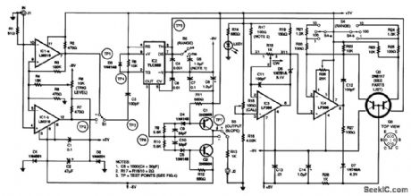
The input stage is the trigger amplifier based on the two channels of an LM319 dual comparator (IC1-a and IC1-b). The in-put signal is taken from the channel 1 output jack of your oscilloscope, and it is applied to J1 on the adapter. The input slope is selected by switch S1, and the signal is coupled to C3 and IC2, the multivibrator stage. Capacitor C3 provides the proper negative-going pulse to trigger IC2, a TLC555 CMOS timing IC. Switch S2 selects the desired range either milliseconds or mi-croseconds-and switch S3 selects the polarity of the output slope. Transistors Q1 and Q2 form a fast (less than 10-ns delay) inverting output stage. The output from switch S3 is ±5 V, which is sufficient for excellent contrast in intensity modulation. It is also satisfactory for stable triggering in the adapter's delayed-sweep mode. Precise input current to capacitors C4 and C5 is supplied from the collector of dual transistor Q3, a 2N5117. It is a dual-matched PNP pair in one package. Operational amplifier IC3, an LF356, is configured as a noninverting follower with gain. Transistor Q3 is configured as an unusual current mirror that unloads the relatively slow operational amplifier, allowing the second half of Q3 to demonstrate its fast dynamic response. A reference voltage is developed across both sets of emitter resistors (R20 to R25) to pro-duce the constant charging current for capacitors C4 and 05. The two sections of switch 54 (S4-a and S4-b) select the range-either 1.0, 10, or 100-in conjunction with switch S2 (milliseconds or microseconds). Zener diodes D6 and D7 permit the operational amplifier outputs to operate in their linear regions. Variable resistor R18 (1 kΩ, 10 turns) is the range multiplier.
Reprinted Url Of This Article:
http://www.seekic.com/circuit_diagram/LED_and_Light_Circuit/DUAL_SCOPE_ADAPTER.html
Print this Page | Comments | Reading(3)

Article Categories
power supply circuit
Amplifier Circuit
Basic Circuit
LED and Light Circuit
Sensor Circuit
Signal Processing
Electrical Equipment Circuit
Control Circuit
Remote Control Circuit
A/D-D/A Converter Circuit
Audio Circuit
Measuring and Test Circuit
Communication Circuit
Computer-Related Circuit
555 Circuit
Automotive Circuit
Repairing Circuit
Code: