Electrical Equipment Circuit
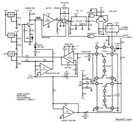
Widest_range_V_F_converter
Published:2009/7/23 23:27:00 Author:Jessie | From:SeekIC

Fig. 12-7 This circuit features a 1-Hz to 100-MHz range with a linearity of 0.06%, 25 ppm/℃temperature coefficient, 50 nV/℃ (0.5 Hz/℃) zero shift, and a 0- to 10-V input range. To calibrate, apply 10.000 V and adjust the 100-MHz trim for 100.00 MHz at the output (if this is beyond counter range, the divide-by-32 signal at pin 16 of the LTC1043 should read 3.1250 MHz). Next, ground the input, install CCOMP (at the noninverting input of A1) and adjust the 1-Hz trim until the circuit oscillates at 1 Hz (use 1 μF for CCOMP). Finally, set the linearity trim for 50.000-MHz output with 5.000 V at the input. Repeat these adjustments until all three points are fixed. Linear Technology Linear Applications Handbook 1990 p AN14-2.
Reprinted Url Of This Article:
http://www.seekic.com/circuit_diagram/Electrical_Equipment_Circuit/Widest_range_V_F_converter.html
Print this Page | Comments | Reading(3)

Article Categories
power supply circuit
Amplifier Circuit
Basic Circuit
LED and Light Circuit
Sensor Circuit
Signal Processing
Electrical Equipment Circuit
Control Circuit
Remote Control Circuit
A/D-D/A Converter Circuit
Audio Circuit
Measuring and Test Circuit
Communication Circuit
Computer-Related Circuit
555 Circuit
Automotive Circuit
Repairing Circuit
Code: