Position: Home > Circuit Diagram > Electrical Equipment Circuit > Voltage_follower_with_increased_accuracy_001_μF
Electrical Equipment Circuit
Voltage_follower_with_increased_accuracy_001_μF
Published:2009/7/24 21:59:00 Author:Jessie | From:SeekIC
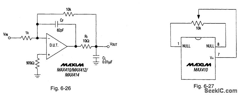
Figure 6-26 shows a voltage follower with increased accuracy (see Fig. 6-1 for pin configurations). The feedback around isolation resistor R1 increases the accuracy and the load capability. To drive capacitive loads greater than 0.01 μF, increase the value of CF. Figure 6-27 shows a null offset circuit suitable for the circuits of Figs. 6-22, 6-24, and 6-26. MAXIM NEW RELEASES DATA BOOK, 1994, P. 3-42.
Reprinted Url Of This Article:
http://www.seekic.com/circuit_diagram/Electrical_Equipment_Circuit/Voltage_follower_with_increased_accuracy_001_μF.html
Print this Page | Comments | Reading(3)

Article Categories
power supply circuit
Amplifier Circuit
Basic Circuit
LED and Light Circuit
Sensor Circuit
Signal Processing
Electrical Equipment Circuit
Control Circuit
Remote Control Circuit
A/D-D/A Converter Circuit
Audio Circuit
Measuring and Test Circuit
Communication Circuit
Computer-Related Circuit
555 Circuit
Automotive Circuit
Repairing Circuit
Code: