Electrical Equipment Circuit
Video_system_channel_control_box
Published:2009/7/22 22:39:00 Author:Jessie | From:SeekIC

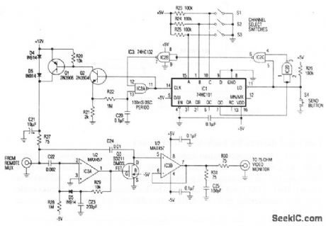
In the channel control box of the single-coax video system (Fig. 3-14), a desired channel is encoded by three bits, set either by switches (as shown) or by an applied digital input. Momentary depression of the send button triggers down-converter IC1 and gated oscillator IC2A to initiate a channel-selection burst.Supply current flows to the remote multiplexor box through Q1 (normally on and saturated), R27, and the coax center conductor. R27 also terminates the coax via C21. When Q1 turns off momentarily, forward bias across D3 and D4 develops a negative 1.2-V channel-select pulse. This 1.2-V drop in supply voltage does not affect the remote multiplexer video output. Consequently, the video monitor display does not flip during channel changes, provided that the channel signals have common sync timing. The short time constant that is associated with coupling of video to the coax (C11 and R9, R27) enables selection of any channel in less than one second, but also allows the video sync-pulse baseline to shift with picture content. To prevent this shift, peak detector IC3A drives Q3, which applies dc restoration ahead of IC3B. During each negative sync pulse, Q3 turns on just long enough to reclamp the pulse tip at 0 V.
Reprinted Url Of This Article:
http://www.seekic.com/circuit_diagram/Electrical_Equipment_Circuit/Video_system_channel_control_box.html
Print this Page | Comments | Reading(3)

Article Categories
power supply circuit
Amplifier Circuit
Basic Circuit
LED and Light Circuit
Sensor Circuit
Signal Processing
Electrical Equipment Circuit
Control Circuit
Remote Control Circuit
A/D-D/A Converter Circuit
Audio Circuit
Measuring and Test Circuit
Communication Circuit
Computer-Related Circuit
555 Circuit
Automotive Circuit
Repairing Circuit
Code: