Electrical Equipment Circuit
Video_amplifier_dc_stabilizer_differentially_sensed_technique
Published:2009/7/22 22:21:00 Author:Jessie | From:SeekIC

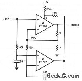
In this circuit, sensing is done differentially, preserving access to both fast amplifier inputs. A1 measures the dc error at the A2 input, and biases the offset pins to force offset within 50 μV. The offset-pin biasing at A2 is arranged so that A1 is always able to find the servo point. The 0.01-μF capacitors rolls off Al at the low frequency, and A2 handles the high-frequency signals. The combined characteristics yield: gain-bandwidth of 45 MHz, offset voltage of 50 μV, offset drift of 1 μV/℃, and a slew rate of 250 V/μs.
Reprinted Url Of This Article:
http://www.seekic.com/circuit_diagram/Electrical_Equipment_Circuit/Video_amplifier_dc_stabilizer_differentially_sensed_technique.html
Print this Page | Comments | Reading(3)

Article Categories
power supply circuit
Amplifier Circuit
Basic Circuit
LED and Light Circuit
Sensor Circuit
Signal Processing
Electrical Equipment Circuit
Control Circuit
Remote Control Circuit
A/D-D/A Converter Circuit
Audio Circuit
Measuring and Test Circuit
Communication Circuit
Computer-Related Circuit
555 Circuit
Automotive Circuit
Repairing Circuit
Code: