Electrical Equipment Circuit
Unity_gain_inverting_wideband_amplifier
Published:2009/7/23 20:57:00 Author:Jessie | From:SeekIC

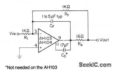
This circuit shows the basic connections in a typical unity-gain inverting amplifier. The use of a compensation capacitor Cc is required for the AN104, unless the gain is fairly high. The AN103 only needs additional external compensation in special cases, such as when used as a noninverting unity-gain follower. Rd in the output circuit improves frequency stability. CF compensates for a pole in the closed-loop transfer function, caused by the input capacitance and feedback resistors. A ground plane is recommended, leads must be short, and Rf should not exceed 5.6 kΩ. Typical bandwidth is 35 MHz, with slew rates of 230 V/μs, into a 330-Ω load
Reprinted Url Of This Article:
http://www.seekic.com/circuit_diagram/Electrical_Equipment_Circuit/Unity_gain_inverting_wideband_amplifier.html
Print this Page | Comments | Reading(3)

Article Categories
power supply circuit
Amplifier Circuit
Basic Circuit
LED and Light Circuit
Sensor Circuit
Signal Processing
Electrical Equipment Circuit
Control Circuit
Remote Control Circuit
A/D-D/A Converter Circuit
Audio Circuit
Measuring and Test Circuit
Communication Circuit
Computer-Related Circuit
555 Circuit
Automotive Circuit
Repairing Circuit
Code: