Telephone-Related Circuit
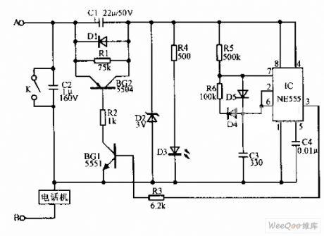
Simple telephone time lock circuit diagram
Published:2011/8/9 18:33:00 Author:Vicky | Keyword: Simple telephone time lock circuit | From:SeekIC

Simple telephone time lock circuit is shown in the above picture. In the circuit diagram, BG1 and BG2 are electronic switches controlled by IC NE555. When the telephone is on-hook, the DC resistance value of the telephone is over 600KΩ, the current when the external line runs into the IC is very low, and the electronic time lock does not work. When the telephone is off-hook, the telephone DC resistance value reduces to 500Ω, and the electronic time lock works. After the call has been made for a certain period of time, pin 3 of the IC turns into low potential, which forces BG1 to stop. The exterior pressure drop is mainly on the electronic switch, which results in the telephone’s inability to work. And the call is suspended.
Reprinted Url Of This Article:
http://www.seekic.com/circuit_diagram/Electrical_Equipment_Circuit/Telephone-Related_Circuit/Simple_telephone_time_lock_circuit_diagram.html
Print this Page | Comments | Reading(3)

Article Categories
power supply circuit
Amplifier Circuit
Basic Circuit
LED and Light Circuit
Sensor Circuit
Signal Processing
Electrical Equipment Circuit
Control Circuit
Remote Control Circuit
A/D-D/A Converter Circuit
Audio Circuit
Measuring and Test Circuit
Communication Circuit
Computer-Related Circuit
555 Circuit
Automotive Circuit
Repairing Circuit
Code: