Electrical Equipment Circuit
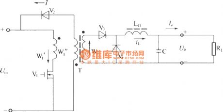
Single end normal shock converter circuit principle diagram
Published:2011/4/11 2:12:00 Author:may | Keyword: Single end, normal shock, converter | From:SeekIC


As shown in the diagram, when switch tube V1 is turn-on, input voltage Uin totally adds to justified of converter primary coil W1', induction voltage generates in degaussing iron ring W1'' make diode V2 cut-off, and induction voltage in secondary coil W2 make V3 turn-on, and sent the power of input current to inductance L0 and capacitance C and load; meanwhile it build up magnetizing current in converter, when V1 cut-off, V3 cut-ff, voltage direction on L0 is rollback andpass diode V4 to power supply to load continued, the magnetizing current in transformer willpass W1'', V 2 to release to input power source Uin and demagnetization; W1 has the function of clamp, the voltage on it is equivalent to input voltage Uin, before V1 turn- on again, demagnetizing current on T must release to zero, namely magnetic flux in T must reset, otherwise, transformer T will saturation and lead to the damage of V1. Normally, W1'=W1'', duty ratio of using two wires parallel winding coupled modes is <0.5, otherwise T will saturation. The wave form of single end normal shock converter is shown in the following diagram.
Reprinted Url Of This Article:
http://www.seekic.com/circuit_diagram/Electrical_Equipment_Circuit/Single_end_normal_shock_converter_circuit_principle_diagram.html
Print this Page | Comments | Reading(3)

Article Categories
power supply circuit
Amplifier Circuit
Basic Circuit
LED and Light Circuit
Sensor Circuit
Signal Processing
Electrical Equipment Circuit
Control Circuit
Remote Control Circuit
A/D-D/A Converter Circuit
Audio Circuit
Measuring and Test Circuit
Communication Circuit
Computer-Related Circuit
555 Circuit
Automotive Circuit
Repairing Circuit
Code: