Electrical Equipment Circuit
Single_chip_low_noise_wideband_amplifier_with_external_gain_AGC
Published:2009/7/24 0:15:00 Author:Jessie | From:SeekIC
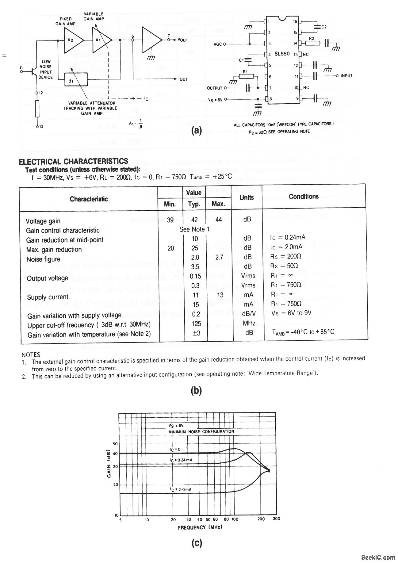
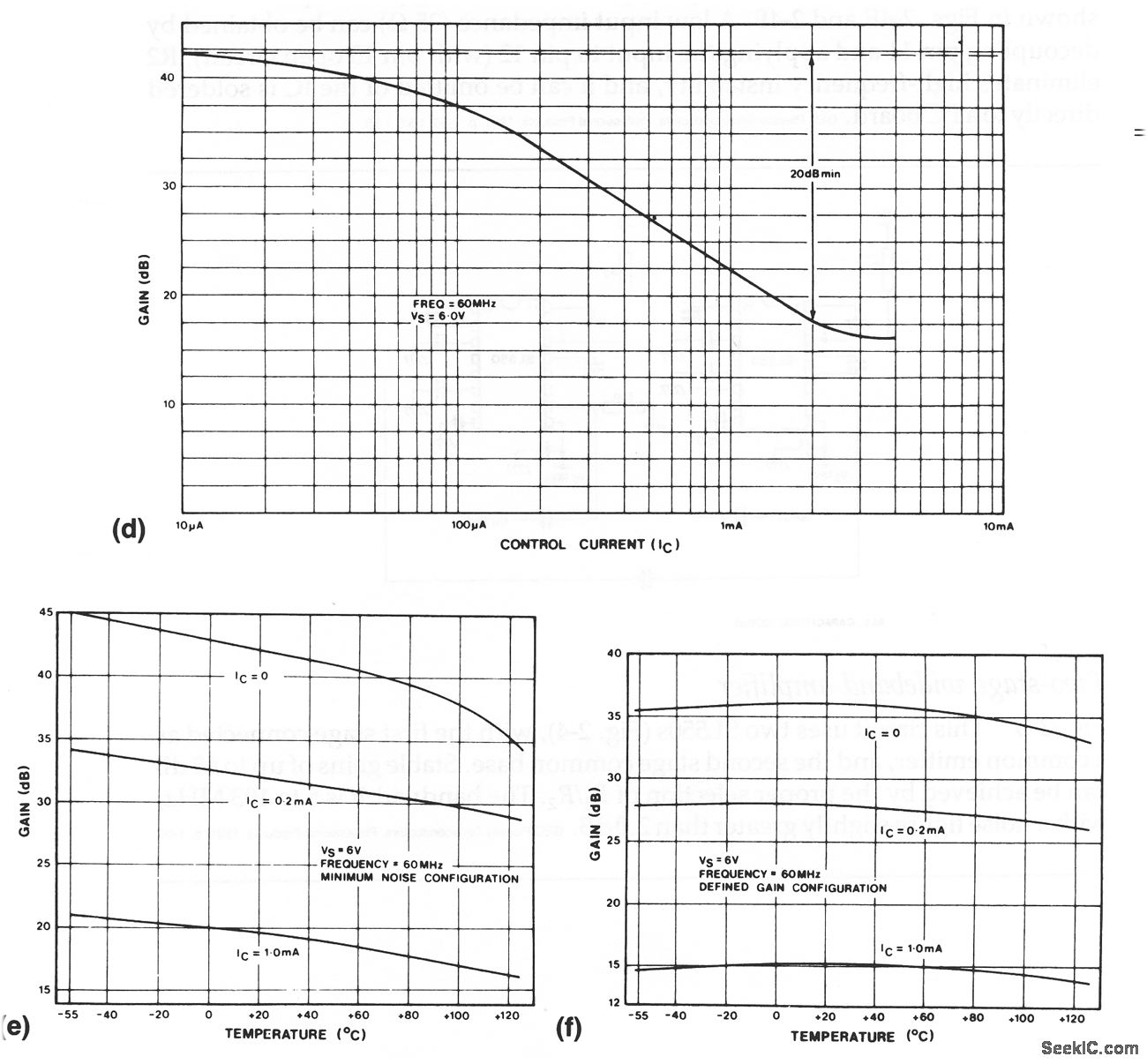
The SL550 used in this circuit is a general-purpose wideband linear amplifier with remote gain/AGC control. Figure 2-4B shows the electrical charac-teristics. Figure 2-4C shows frequency response. The input capacitance (typically 12 pF at 60 MHz) is independent of frequency. The input resistance (about 1.5 kΩ at 10 MHz) decreases with frequency and is typically 500Ω at 60 MHz. Typical gain/ACC voltage is 0.6 V (Ic=1μA) to 0.8 v (IC= 2 mA) applied to pins 2 and 3 (Fig. 2-4D). If full output swing is not required, omit R1, as shown in Fig. 2-4B.A high-impedance output current can be obtained by taking the output from pin 6 (with pin 7 open circuit). Maximum output current is 2 mA peak, with an output impedance of 350 Ω. Gain variation with temperature can be reached (at the expense of noise figure) by decoupling pin 13 and leaving pin 12 open circuit, as shown in Figs. 2-4E and 2-4F. A low input impedance (25 Ω) can be obtained by decoupling pin 11 and applying the input to pin 12 (with pin 13 open circuit). R2 eliminates high-frequency instability, and it can be omitted of the IC is soldered directly to a PC board.
Reprinted Url Of This Article:
http://www.seekic.com/circuit_diagram/Electrical_Equipment_Circuit/Single_chip_low_noise_wideband_amplifier_with_external_gain_AGC.html
Print this Page | Comments | Reading(3)

Article Categories
power supply circuit
Amplifier Circuit
Basic Circuit
LED and Light Circuit
Sensor Circuit
Signal Processing
Electrical Equipment Circuit
Control Circuit
Remote Control Circuit
A/D-D/A Converter Circuit
Audio Circuit
Measuring and Test Circuit
Communication Circuit
Computer-Related Circuit
555 Circuit
Automotive Circuit
Repairing Circuit
Code: