Other Circuit
Grid Electrode Drivng Circuit Composed Of M57918L
Published:2011/8/17 0:30:00 Author: | Keyword: Grid, Electrode, Drivng | From:SeekIC

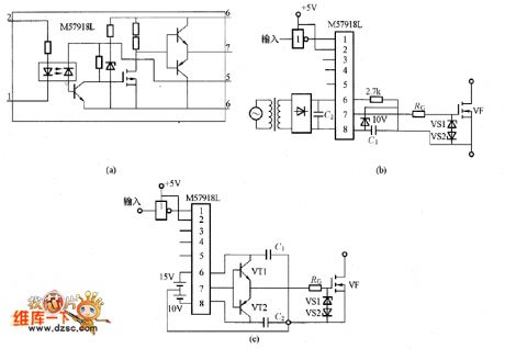
The picture shows the the grid electrode driving circuit composed of M57918L. The picture (a) is the M57918L internal equivalent circuit. The picture (b) shows the circuit driving the low-power MOSFET. In the circuit the C1 and C2's capacity is more than 200 times than Ciss (the input capacitanc of the MOSFET). If using the electrolytic capacitor, it needs to add the film capacitor in parallel with electrolytic capacitor and the film capacitor should have good high-frequency features. Its capacity is 1/200 of the C1 or C2's capacitor. The lower of the RG, the higher the switching speed would be, but it shouldn't be lower than its lower limit. The VS1 and VS2 need the regulator diode about 18V. The picture (c) is the circuit which is driving the large-power MOSFET.
Reprinted Url Of This Article:
http://www.seekic.com/circuit_diagram/Electrical_Equipment_Circuit/Other_circuit/Grid_Electrode_Drivng_Circuit_Composed_Of_M57918L.html
Print this Page | Comments | Reading(3)

Article Categories
power supply circuit
Amplifier Circuit
Basic Circuit
LED and Light Circuit
Sensor Circuit
Signal Processing
Electrical Equipment Circuit
Control Circuit
Remote Control Circuit
A/D-D/A Converter Circuit
Audio Circuit
Measuring and Test Circuit
Communication Circuit
Computer-Related Circuit
555 Circuit
Automotive Circuit
Repairing Circuit
Code: