Other Circuit
Dual Tuning Frequency Detector Circuit
Published:2011/8/23 23:41:00 Author:Robert | Keyword: Dual, Tuning, Frequency, Detector | From:SeekIC

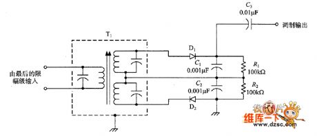
A classic FM frequency detector circuit is shown in the picture. The circuit uses a special transformer which has two secondary windings. The two secondary windings are separately connected to the two sides of the IF frequency which have the same distance to IF frequency and are not fay from the IF frequency. The two frequency's distance should be a little bigger than the transmitter's amplitude. The output would combine through a couple differencial signal diodes (D1 and D2). The diodes' output ports are connected to the load resistor R1 and R2. Generally, when the signal has not been modulated, the algebraic sum of the two diodes' output is zero. That would make the output be zero.
Reprinted Url Of This Article:
http://www.seekic.com/circuit_diagram/Electrical_Equipment_Circuit/Other_circuit/Dual_Tuning_Frequency_Detector_Circuit.html
Print this Page | Comments | Reading(3)

Article Categories
power supply circuit
Amplifier Circuit
Basic Circuit
LED and Light Circuit
Sensor Circuit
Signal Processing
Electrical Equipment Circuit
Control Circuit
Remote Control Circuit
A/D-D/A Converter Circuit
Audio Circuit
Measuring and Test Circuit
Communication Circuit
Computer-Related Circuit
555 Circuit
Automotive Circuit
Repairing Circuit
Code: