Electrical Equipment Circuit
Metamorphous half-bridge type convertor circuit principle diagram
Published:2011/4/7 19:56:00 Author:may | Keyword: Metamorphous, half-bridge type convertor | From:SeekIC
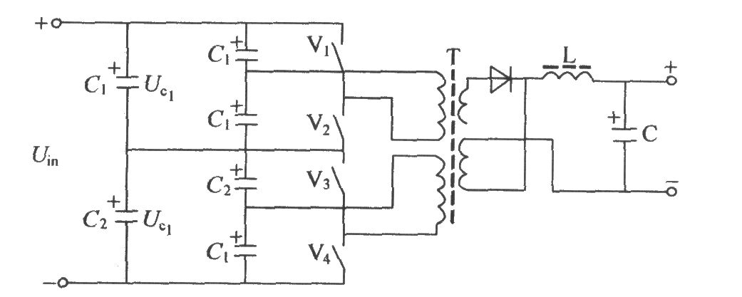
We usually adopt the circuit mode in the diagram in the situation of high voltage input, high power output. In the circuit, switching element V1, V2 is a group, V3, V4 is a group, series each other, which can reduce single tube withstand voltage. In practical application circuit, switching element V1, V2, V3, V4 can use two tubes or multi-tube parallel. In this way can solve the problem of high current output. Sharing transformer can increase the operating factor of transformer and have the ability of resisting imbalance. In metamorphous half-bridge type power converting circuit, V1, V2 or V3, V4, the maximum each switching tube withstand voltage only is Uc1 or Uc2 value. If C1=C2, than Uc1=Uc2=Uin/2 value, so we can choose switching tube of reducing withstand voltage. In addition, V1, V2, V3, V4 can adopts multi-tube parallel mode to work, which can add the capacity of output current; it greatly raise the efficiency of transformer that transformer T can working at positive and negative direction. Because of merit above-mentioned, this circuit has widespread use, especially in the situation of high voltage input and high power output. The application of this circuit is more and more widespread.
Reprinted Url Of This Article:
http://www.seekic.com/circuit_diagram/Electrical_Equipment_Circuit/Metamorphous_half_bridge_type_convertor_circuit_principle_diagram.html
Print this Page | Comments | Reading(3)

Article Categories
power supply circuit
Amplifier Circuit
Basic Circuit
LED and Light Circuit
Sensor Circuit
Signal Processing
Electrical Equipment Circuit
Control Circuit
Remote Control Circuit
A/D-D/A Converter Circuit
Audio Circuit
Measuring and Test Circuit
Communication Circuit
Computer-Related Circuit
555 Circuit
Automotive Circuit
Repairing Circuit
Code: