Electrical Equipment Circuit
MEASURING_SCR_TURNOFF_TIME
Published:2009/7/23 21:48:00 Author:Jessie | From:SeekIC


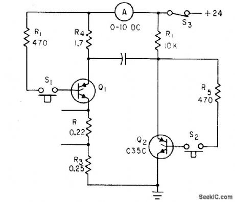
Q1 in parallel inverter circuit is triggered by dosing S1, to give 10 amp of test current. When S2 is closed after warmup, Q2 turns on, connects positively charged plate of C1 to cathode of Q1, and makes reverse current flow. If turnoff lime of Q1 is less than 12 microsec, it will remain turned off and ammeter reading will return to zero. If test rectifier fails to turn off, S3 should be opened immediately each drive monostable mvbr, with output to prevent overheating.-D. V. Jones, Turn-Off Circuits for Controlled Rectifiers, Electronics, 33:32, p 52-55.
Reprinted Url Of This Article:
http://www.seekic.com/circuit_diagram/Electrical_Equipment_Circuit/MEASURING_SCR_TURNOFF_TIME.html
Print this Page | Comments | Reading(3)

Article Categories
power supply circuit
Amplifier Circuit
Basic Circuit
LED and Light Circuit
Sensor Circuit
Signal Processing
Electrical Equipment Circuit
Control Circuit
Remote Control Circuit
A/D-D/A Converter Circuit
Audio Circuit
Measuring and Test Circuit
Communication Circuit
Computer-Related Circuit
555 Circuit
Automotive Circuit
Repairing Circuit
Code: