Electrical Equipment Circuit
Line_isolation
Published:2009/7/23 23:48:00 Author:Jessie | From:SeekIC

In telecom systems, the service provider incorporates line isolation to protect the network against unorthodox connections made by users. At the other end of the line, EIA-232D connections used in medical patient-monitoring equipment, data loggers, and supervisory computers (to name a few devices) must be isolated to protect the equipment from hardware failures. Isolation not only provides safety, but it can improve system performance.
As an example, EIA-232D links between a computer in one building and terminals in another building can show ground-current noise if the building earth-ground connections are at different potentials (as is usually the case). Isolation with a rating of 100 V can solve this problem. In severe industrial environments, a full UL-listed isolation barrier of 1500 V (or more) might be required.
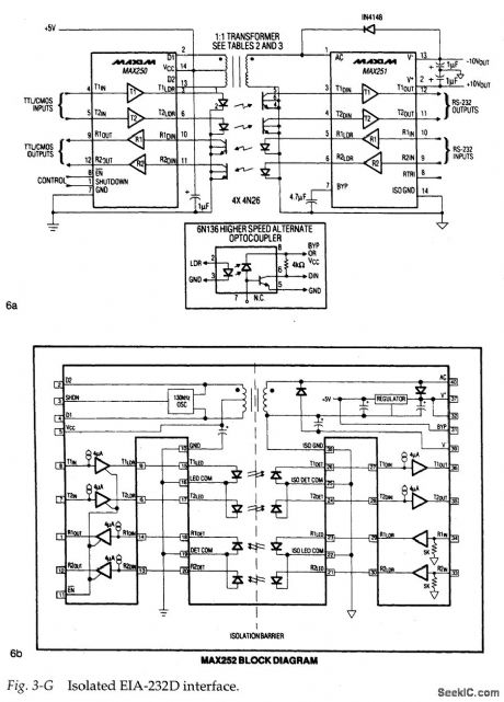
The transmission of digital data, while maintaining an electrical barrier, usually involves transformers and opto-isolators, as shown in 6a of Fig. 3-G. The transformer supplies power to the other side of the barrier, and the opto-couplers handle data transmission across the barrier. However, there is a problem with this approach. The LEDs in opto-isolators (especially high-speed opto-isolators) require more current than normal logic circuits can provide. As a result, you must connect the outputs in parallel or add buffer ICs to get adequate drive current. Also, the isolated power supply must be fairly large because standard EIA-232D chips require a supply voltage of ±12V, as well as +5 V.
One approach to solving these power and data-transfer problems is to use matching interface chip sets, such as the MAX250/MAX251, shown in 6a of Fig. 3-G. These two ICs include circuitry for two EIA-232D transmitters and two receivers, circuitry for generating isolated power-supply voltage from the main (non-isolated) +5-V supply, and interface circuitry for driving and receiving signals from the external opto-isolators. You only need to supply the isolators, a 1:1 transformer, and a few passive components to complete an isolated dual-transceiver EIA-232D port. (Such circuits are covered in this chapter)
The alternate approach is to use a single-chip interface, such as the MAX252 shown in 6b of Fig. 3-G. This IC includes all of the circuitry in a standard 40-pin DIP, but provides the full UL-recognized 1500-V isolation barrier. (This approach is also covered in this chapter.)
Reprinted Url Of This Article:
http://www.seekic.com/circuit_diagram/Electrical_Equipment_Circuit/Line_isolation.html
Print this Page | Comments | Reading(3)

Article Categories
power supply circuit
Amplifier Circuit
Basic Circuit
LED and Light Circuit
Sensor Circuit
Signal Processing
Electrical Equipment Circuit
Control Circuit
Remote Control Circuit
A/D-D/A Converter Circuit
Audio Circuit
Measuring and Test Circuit
Communication Circuit
Computer-Related Circuit
555 Circuit
Automotive Circuit
Repairing Circuit
Code: