© 2008-2012 SeekIC.com Corp.All Rights Reserved.
Electrical Equipment Circuit
Electronic Organ Circuit
Published:2012/9/27 21:37:00 Author:muriel | Keyword: Electronic Organ | From:SeekIC


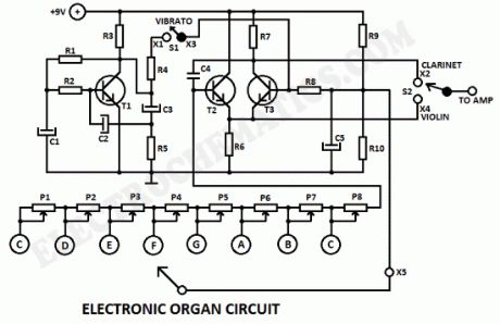
This electronic organ circuit is very simple to construct and is basically an emitter-coupled oscillator composed of T2 and T3. An squarewave voltage can be sampled from the collector of T3 (X2). This signal gives a clarinet character to the tone.Without the squarewave signal, the sound produced by emitters of T2 and T3 (X4) has a violin character. An additional vibrato signal can be added to this basic sound through switch S1. The frequency of the vibrato is around 6 Hz. Its amplitude is determined by the R4. The value of R4 can vary from 100 up to 300KΩ but you can experiment with different values.
The organ keys can be made of either metal plates or etched printed circuit.The trimmers P1 up to P8 adjust the pitch of each tone. The tones can be drastically changed by changing the value of C4.
Electronic Organ circuit diagram
Printed Circuit Board for the Electronic Organ
Reprinted Url Of This Article:
http://www.seekic.com/circuit_diagram/Electrical_Equipment_Circuit/Electronic_Organ_Circuit.html
Print this Page | Comments | Reading(3)

Article Categories
power supply circuit
Amplifier Circuit
Basic Circuit
LED and Light Circuit
Sensor Circuit
Signal Processing
Electrical Equipment Circuit
Control Circuit
Remote Control Circuit
A/D-D/A Converter Circuit
Audio Circuit
Measuring and Test Circuit
Communication Circuit
Computer-Related Circuit
555 Circuit
Automotive Circuit
Repairing Circuit
New published articles
Response in 12 hours

Code: