Electrical Equipment Circuit
Children anti-lost reminder circuit
Published:2011/10/24 1:35:00 Author:May | Keyword: Children anti-lost reminder | From:SeekIC


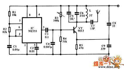
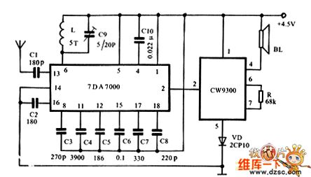
Figure 1 shows the transmitter circuit. It consists of time-base IC NE555, R1, R2, C1. 1KHz low-frequency oscillator can modulate the high-frequency oscillator composed of transistor VT and peripheral components, then the modulated high-frequency signal is sent out by the inside tiny antenna from the C7. C8 is used to add broadband and prevent impact on the frequency from human induction. Actual use proves that it is the essential element. Figure 2 shows the receiver circuit. When the receiver receives the signal sent by the transmitter, the pin ② of IC TDA7000 outputs low level, the music IC CW9300 has no high level to trigger signal and does not work, then speaker BL is silent.
Reprinted Url Of This Article:
http://www.seekic.com/circuit_diagram/Electrical_Equipment_Circuit/Children_anti_lost_reminder_circuit.html
Print this Page | Comments | Reading(3)

Article Categories
power supply circuit
Amplifier Circuit
Basic Circuit
LED and Light Circuit
Sensor Circuit
Signal Processing
Electrical Equipment Circuit
Control Circuit
Remote Control Circuit
A/D-D/A Converter Circuit
Audio Circuit
Measuring and Test Circuit
Communication Circuit
Computer-Related Circuit
555 Circuit
Automotive Circuit
Repairing Circuit
Code: