© 2008-2012 SeekIC.com Corp.All Rights Reserved.
Electrical Equipment Circuit
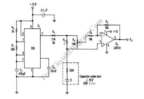
Capacitor ESR Meter circuit
Published:2013/3/29 4:25:00 Author:Ecco | Keyword: Capacitor ESR Meter | From:SeekIC

This is schematic diagram of capacitor ESR meter circuit. ESR is equivalent series resistance, and this parameter is used to express the resistance value of any electronic component that basically is not a resistor. ESR is present on many non-resistor component, such as capacitor, inductor, or semiconductor. The circuit shown in this schematic diagram is used to measure equivalent series resistance (ESR) of a capacitor. This ESR meter circuit uses 555 IC as 50-kHz square-wave generator. The ±180mA current waveform is driven in the capacitor-under-test by U1, through R2 and R1. Adjust R3 to the proper value, the inverting amplifier (U2) will null the voltage drop across the equivalent series resistor. The minimum voltage that can be produced at VO the pure capacitor voltage. Here is the schematic diagram of the circuit:
Reprinted Url Of This Article:
http://www.seekic.com/circuit_diagram/Electrical_Equipment_Circuit/Capacitor_ESR_Meter_circuit.html
Print this Page | Comments | Reading(3)

Article Categories
power supply circuit
Amplifier Circuit
Basic Circuit
LED and Light Circuit
Sensor Circuit
Signal Processing
Electrical Equipment Circuit
Control Circuit
Remote Control Circuit
A/D-D/A Converter Circuit
Audio Circuit
Measuring and Test Circuit
Communication Circuit
Computer-Related Circuit
555 Circuit
Automotive Circuit
Repairing Circuit
New published articles
Response in 12 hours

Code: