Electrical Equipment Circuit
Boost and output practical circuit
Published:2011/11/22 0:42:00 Author:May | Keyword: Boost, output, practical | From:SeekIC

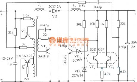
The diagram is a boost andoutput practical circuit. VT3 is switching regulating tube. Regulation tube VD2 can convert the potential. VT4 is paraphrase isolation amplifier. VT4 and its load which is 33kΩ resistor will divide the voltage Ui. The two voltages are separately provided to impulse generator. Impulse generator consists of transformer T and VT1, VT2. This is free running multi-vibrator of asymmetric transformer positive feedback. The power of VT1 comes from the voltage on 33kΩ resistor. The current on resistor depends on the current of VT4. The power supply voltage of VT1, VT2 is different. Each half period oscillation amplitude changes in direct proportion, the width changes in inverse proportion. Then it can control the turn-on and cut-off time. When output voltage is increasing, the current of differential pair tube VT6 of error amplifier is decreasing, collector potential is increasing, 33kΩ resistor up voltage drop is enlarge, VT1 tube power supply voltage is increasing, the turn on time is shortening, switching tube VT3’s turn on time is shortening.
The input voltage of this circuit is 12~28V, the output can be stabilized at 30V, the maximum output power is 60W, the efficiency is 88.9%~94.7%, the instability degree is ±0.33%, the output voltage ripple factor is 0.02&, the working frequency is 10kHz.
Reprinted Url Of This Article:
http://www.seekic.com/circuit_diagram/Electrical_Equipment_Circuit/Boost_and_output_practical_circuit.html
Print this Page | Comments | Reading(3)

Article Categories
power supply circuit
Amplifier Circuit
Basic Circuit
LED and Light Circuit
Sensor Circuit
Signal Processing
Electrical Equipment Circuit
Control Circuit
Remote Control Circuit
A/D-D/A Converter Circuit
Audio Circuit
Measuring and Test Circuit
Communication Circuit
Computer-Related Circuit
555 Circuit
Automotive Circuit
Repairing Circuit
Code: