Electrical Equipment Circuit
Automatic washing circuit
Published:2011/8/17 20:46:00 Author:Jessie | Keyword: Automatic washing | From:SeekIC

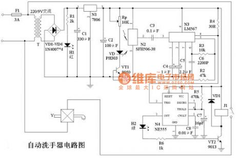
The principle of automatic washing circuit is shown in figure 1, and220VAC circuitis bucked by transformer T, and it changes to low voltage current. Then it is regulated by three terminal voltage circuit 7806 toget 6VDC to supply to control circuit. H1is a red led, which is used as a power supply instruction. N2 is theinfrared receiving circuit SFH506-38, and N3is PLL audio decoder LM567, and N3 and R3, C6form an oscillator, and R3, R6 decide the center frequency of N3's internal vco. LM567's pin 3 is the signal input,pin 8 islogic output, its output terminal is OC door output, max irrigation current is 100mA, the working voltage of LM567is 4.75 V ~ 9V. Working frequency can be from a few Hz to 500 KHZ, andthestatic working current is8mA. N4 isNE555 timer, andits peripheral componentsform the single state timing circuit, the purpose is to guarantee the normal water for washing hands when hands occasionally deviate infrared's detection range.
Reprinted Url Of This Article:
http://www.seekic.com/circuit_diagram/Electrical_Equipment_Circuit/Automatic_washing_circuit.html
Print this Page | Comments | Reading(3)

Article Categories
power supply circuit
Amplifier Circuit
Basic Circuit
LED and Light Circuit
Sensor Circuit
Signal Processing
Electrical Equipment Circuit
Control Circuit
Remote Control Circuit
A/D-D/A Converter Circuit
Audio Circuit
Measuring and Test Circuit
Communication Circuit
Computer-Related Circuit
555 Circuit
Automotive Circuit
Repairing Circuit
Code: