Control Circuit
sound surface wave resonator application circuit in the wireless remote control
Published:2011/7/9 9:43:00 Author:Lena | Keyword: sound surface wave, resonator, application circuit, wireless remote control | From:SeekIC
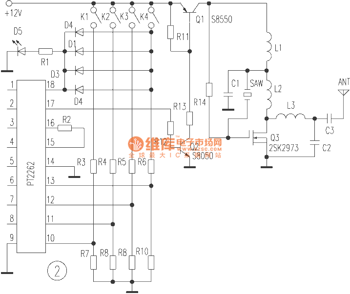

R11-R13, Q1 and Q2 form electron switch modulation circuit, when encoder outputs high level, Q1 conducts, and oscillator emitter electrode works. When encoder outputs low level, Q1 stops to complete ASK modulation. R14, Q3, C1, L1, L2 and sound surface resonator SAW constitutes 315MHZ power master oscillator, Q3 is a high frequency field effect transistor, which can output 1.5W power at 450MHz.
Reprinted Url Of This Article:
http://www.seekic.com/circuit_diagram/Control_Circuit/sound_surface_wave_resonator_application_circuit_in_the_wireless_remote_control.html
Print this Page | Comments | Reading(3)

Article Categories
power supply circuit
Amplifier Circuit
Basic Circuit
LED and Light Circuit
Sensor Circuit
Signal Processing
Electrical Equipment Circuit
Control Circuit
Remote Control Circuit
A/D-D/A Converter Circuit
Audio Circuit
Measuring and Test Circuit
Communication Circuit
Computer-Related Circuit
555 Circuit
Automotive Circuit
Repairing Circuit
Code: