Control Circuit
VOLTAGE_REGULATOR_FOR_A_PROJECTION_LAMP
Published:2009/7/1 1:12:00 Author:May | From:SeekIC
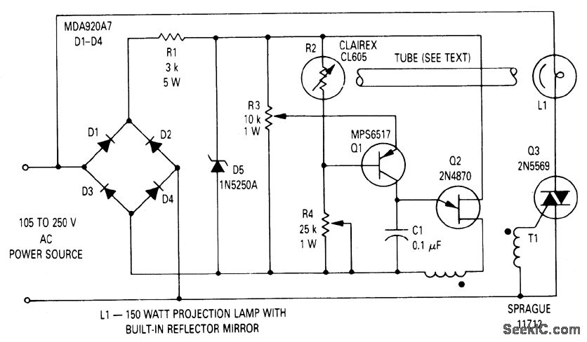
The circuit will regulate the rms output voltage across the load (a projection lamp) to 100 volts 12% for an input voltage between 105 and 250 volts ac. This is accom-plished by indirectly sensing the light output of lamp L1 and applying this feedback signal to the firing circuit (Q1 and Q2) which controls the conduction angle of TRIAC Q3. The lamp voltage is provided by TRIAC Q3, whose conduction angle is set by the firing circuit for unijunction transistor Q2. The circuit is synchronized with the line through the full-wave bridge rectifier. The voltage to the firing circuit is limited by zener diode D5. Phase control of the supply voltage is set by the charging rate of capacitor C1. Q2 will fire when the voltage on C1 reaches approximately 0.65 times the zener voltage. The charging rate of C1 is set by the conduction of Q1, which is controlled by the resistance of photocell R2. Potentiometers R3 and R4 are used to set the lamp voltage to 100 volts when the line voltage is 105 volts and 250 volts, respectively.
Reprinted Url Of This Article:
http://www.seekic.com/circuit_diagram/Control_Circuit/Voltage_regulator_for_a_projection_lamp.html
Print this Page | Comments | Reading(3)

Article Categories
power supply circuit
Amplifier Circuit
Basic Circuit
LED and Light Circuit
Sensor Circuit
Signal Processing
Electrical Equipment Circuit
Control Circuit
Remote Control Circuit
A/D-D/A Converter Circuit
Audio Circuit
Measuring and Test Circuit
Communication Circuit
Computer-Related Circuit
555 Circuit
Automotive Circuit
Repairing Circuit
Code: