Control Circuit
Undervoltage,overvoltage protection alarm circuit
Published:2011/7/9 2:07:00 Author:Fiona | Keyword: undervoltage,overvoltage protection, alarm | From:SeekIC


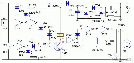
Work principle
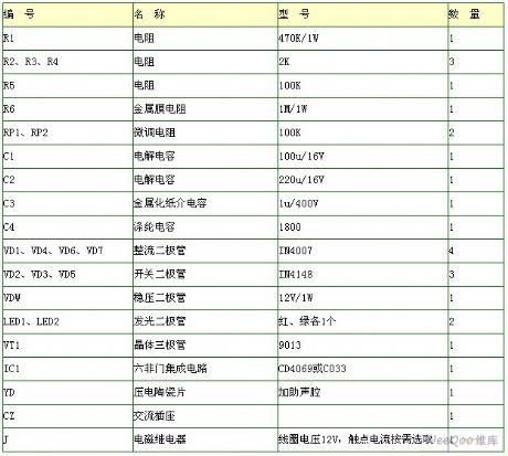
Circuit is shown as above.Mains voltage reduces voltage by C3,maintains voltage by DW,VD6,VD7,C2 rectifier filter output maintaining DC voltage supply circuit.Another path is rectified by VD1,reduced voltage by R1 and filtered by C1, the voltage about 12V produced in RP1、RP2 detects the input signal of the mains voltage change.Door IC1A,IC1B form the overvoltage detection circuit, IC1C is undervoltage detection,IC1D is switch,IC1E,IC1F,piezoelectric ceramicchip YD and other components form the audio pulse oscillator. Transistor VT,relay J and other components form the protection movement circuit.Red LED1 is for mains overvoltage indication,the green LED2 is for mains voltage undervoltage indication.
Reprinted Url Of This Article:
http://www.seekic.com/circuit_diagram/Control_Circuit/Undervoltageovervoltage_protection_alarm_circuit.html
Print this Page | Comments | Reading(3)

Article Categories
power supply circuit
Amplifier Circuit
Basic Circuit
LED and Light Circuit
Sensor Circuit
Signal Processing
Electrical Equipment Circuit
Control Circuit
Remote Control Circuit
A/D-D/A Converter Circuit
Audio Circuit
Measuring and Test Circuit
Communication Circuit
Computer-Related Circuit
555 Circuit
Automotive Circuit
Repairing Circuit
Code: