Control Circuit
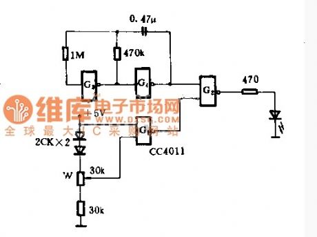
Undervoltage alarm circuit diagram
Published:2014/3/13 22:58:00 Author:lynne | Keyword: Undervoltage alarm circuit diagram, | From:SeekIC

This circuit is a low-pressure alarm circuit 5V power supply, only one and not gate CC4011, with LED indication. Circuit is simple, reliable, low-power consumption. Supply voltage is high enough, G1 output low, G2 output high, light-emitting diodes. When the supply voltage drops to the set value, an input terminal of the G3 becomes a low voltage, high output G1. Thus, the pulse oscillator G3, G4 composition produced by the light emitting diode G2 flash frequency of the oscillator frequency, three times per second.When mediation, just need power plus the minimum allowable value (eg 4V), then change the position of the potentiometer arm, so that the output of G1 can just flip.
Reprinted Url Of This Article:
http://www.seekic.com/circuit_diagram/Control_Circuit/Undervoltage_alarm_circuit_diagram.html
Print this Page | Comments | Reading(3)

Article Categories
power supply circuit
Amplifier Circuit
Basic Circuit
LED and Light Circuit
Sensor Circuit
Signal Processing
Electrical Equipment Circuit
Control Circuit
Remote Control Circuit
A/D-D/A Converter Circuit
Audio Circuit
Measuring and Test Circuit
Communication Circuit
Computer-Related Circuit
555 Circuit
Automotive Circuit
Repairing Circuit
Code: