Index 307
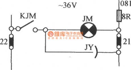
JHo-751 Semi-automatic cargo elevator lighting circuit (2)
Published:2011/3/28 1:26:00 Author:Jessie | Keyword: Semi-automatic, cargo elevator, lighting
View full Circuit Diagram | Comments | Reading(384)
ISO113 offset voltage-regulating circuit
Published:2011/3/28 22:05:00 Author:may | Keyword: offset voltage-regulating
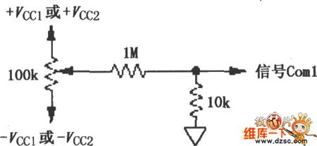
The diagram is ISO113 offset voltage-regulating circuit. This circuit can adjust offset voltage, adjust output and add to signal input common end Com1, offer ±150mV adjust range.
(View)
View full Circuit Diagram | Comments | Reading(531)
Electric fan reactor speed circuit
Published:2011/3/28 21:58:00 Author:may | Keyword: Electric fan reactor speed
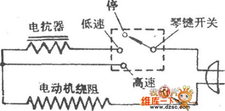
Electric fan reactor speed circuit is shown in the diagram:
(View)
View full Circuit Diagram | Comments | Reading(372)
Pyroelectric infrared detector and its application circuit diagram
Published:2011/3/31 3:19:00 Author:Jessie | Keyword: Pyroelectric infrared detector, application
View full Circuit Diagram | Comments | Reading(517)
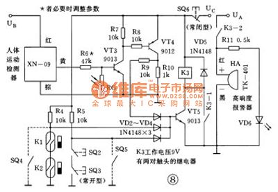
Pyroelectric infrared language alarm circuit
Published:2011/3/31 3:50:00 Author:Jessie | Keyword: Pyroelectric infrared language alarm
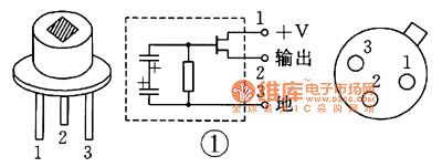
Pyroelectric infrared language alarm isuse pyroelectricity infrared sensor as the probe todetect human body's special wavelength infrared signal. Non-contact detection distance, that is the body close to the protected areas' vision, alarm devicewill send outwarninglanguage. Sensor'sspectral rangeis 1 ~ 10μm, center is 6 μm, all All are in infrared bands, is decided by the optical properties of silicon window which packed in TO-5 metal shell.
(View)
View full Circuit Diagram | Comments | Reading(705)
Pyroelectric infrared language alarm device selection circuit
Published:2011/3/30 3:09:00 Author:Jessie | Keyword: infrared language, alarm device
Pyroelectric infrared sensor modelcan choose P2288 or LS064, need to match 120 ° 12m wide-angle Fresnel filter glass. IC1 choose SNS9201 integrated circuit or SS0001 application-specific integrated circuit. IC2is language integrated circuits BA08, it storesstatement of Dangerous, there is electricity, keep away , IC2is soft encapsulation. IC3 is a integrate circuit with four languages analog sound, working voltageis 2 4 ~ 5 5V, soft encapsulation.
(View)
View full Circuit Diagram | Comments | Reading(584)
Voice-control switch and amplifier circuit
Published:2011/3/23 3:02:00 Author:Joan | Keyword: Voice-control switch , amplifier , Voice-control
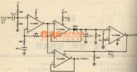
Below is Voice-control switch and amplifier circuit.
(View)
View full Circuit Diagram | Comments | Reading(470)
Acoustic control four tones doll principle circuit diagram
Published:2011/3/28 1:30:00 Author:Joan | Keyword: Acoustic control , four tones , doll
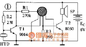
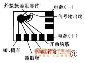
This circuit uses the FL-11 blocks. It has few external components and its device is simple. Connect a ready acoustic control PCB to 2 1/4 inch speakers. Load into a box, and then external connect toFour AA batteries storm cells and support. Switch on, put into the doll body. When clapping, the doll cries of father, mother. It sounds like real one. the circuit generally can be succeed by different debug.
(View)
View full Circuit Diagram | Comments | Reading(829)
Voice-control doll PCB circuit
Published:2011/3/23 3:00:00 Author:Joan | Keyword: Voice-control doll , PCB , Voice-control
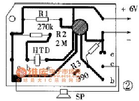
Below is Voice-control doll PCB circuit.
(View)
View full Circuit Diagram | Comments | Reading(454)
Multi-functional fountain bonsai operation principle circuit
Published:2011/3/27 23:03:00 Author:Joan | Keyword: Multi-functional fountain bonsai , operation principle
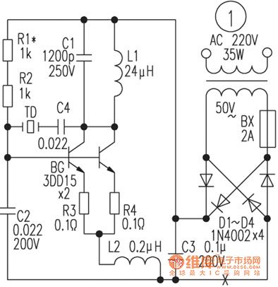
It is a high-power and high-frequency oscillator using capacitive three-point oscillating circuit. The circuit oscillation frequency is piezoelectric transducer TD’s natural frequency 1.3MHz. L1 and C1 form a resonant circuit which does not determine the oscillation frequency here, but decided the oscillation amplitude. Its resonant frequency is 0.6MHz lower than the circuit's oscillation frequency. L2 and C2 oscillation frequency is greater than the circuit resonant frequency. The reason for using two resonant circuits, is to make the oscillation frequency of the circuit is more pure. To make the work of the oscillator is stable in the high-power, it uses two transistors to parallel work. R1, R2 are bias resistors. R1 is adjusted to make the oscillator output moderate. R3, R4 are used to balance the two transistors. (View)
View full Circuit Diagram | Comments | Reading(1102)
Simple infrared alarm device circuit
Published:2011/3/30 2:25:00 Author:Jessie | Keyword: infrared, alarm device
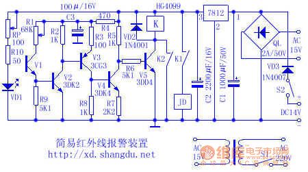
Infrared alarm device emits an infrared,can not be seen only by the naked eye, when anyone or object blocking any bunch of infrared light, alarm devicewill immediately makewarning signals.Using infraredto makealarm device, has advantages of concealed, high reliability, long life, strong anti-jamming capability, etc.
(View)
View full Circuit Diagram | Comments | Reading(1015)
The human body induction alarm cat diagram
Published:2011/3/31 3:18:00 Author:Jessie | Keyword: human body induction alarm cat
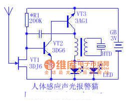
When debugging, first adjust oscillating circuit part,don't access mosfet to circuit temporarily. As long as oscillation part welding and correct, itwill send out Mimi quack, meanwhile leds can glow normal, changing the feedback capacitor C can change oscillation frequency, small capacity, high frequency, whereas low frequency. Then access mosfetto circuit, switch on the power, HTD calls appear, it's dueto human body's induction.
(View)
View full Circuit Diagram | Comments | Reading(665)
Stationary three end stabilizer output voltage adjustable circuit
Published:2011/3/30 2:18:00 Author:Jessie | Keyword: three end stabilizer, output voltage adjustable
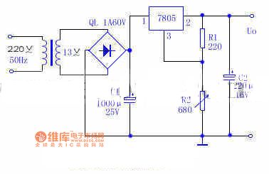
R1 is220Ω, R2 is 680Ω, they aremainly used to adjust output voltage. Output voltage Uo≈Uxx(1+R2/R1), this circuit can realizeoutput voltage continuous adjustable in voltage range of 5~12V. Experiments prove: (1) R1is afixed resistance, change its value can obtained continuous adjustable output voltage, output voltage is equal to Uxx(1 + R2 / R1); (2) The supreme output voltage is limited by stabilizer's maximum input voltage and minimum input/output voltage, so this circuit's maximum outputis 12V; (3) Withinrange of the voltage regulator, the regulator precision can reach ±0.03.
(View)
View full Circuit Diagram | Comments | Reading(382)
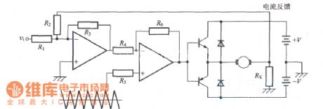
Current control circuit with PWM
Published:2011/3/31 1:50:00 Author:Jessie | Keyword: Current control, PWM
View full Circuit Diagram | Comments | Reading(499)
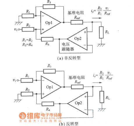
Voltage-current conversion circuit
Published:2011/3/30 3:22:00 Author:Jessie | Keyword: voltage-current conversion
View full Circuit Diagram | Comments | Reading(344)
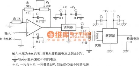
AC voltage detected circuit diagram with carrier
Published:2011/3/31 1:40:00 Author:Jessie | Keyword: AC voltage detected, carrier
View full Circuit Diagram | Comments | Reading(461)
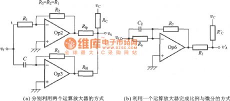
Proportion feedback and differential feedback circuit
Published:2011/3/31 1:31:00 Author:Jessie | Keyword: Proportion feedback, differential feedback
View full Circuit Diagram | Comments | Reading(353)
Pressurization circuits (charging pump) diagram with LTC3200
Published:2011/3/31 1:30:00 Author:Jessie | Keyword: Pressurization, charging pump
View full Circuit Diagram | Comments | Reading(406)
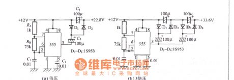
Using the Timer IC to step up circuit
Published:2011/3/30 1:49:00 Author:Jessie | Keyword: Timer IC, step up
View full Circuit Diagram | Comments | Reading(380)
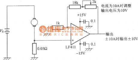
Current detection circuit
Published:2011/3/30 1:40:00 Author:Jessie | Keyword: Current detection
View full Circuit Diagram | Comments | Reading(423)
| Pages:307/312 At 20301302303304305306307308309310311312 |
Circuit Categories
power supply circuit
Amplifier Circuit
Basic Circuit
LED and Light Circuit
Sensor Circuit
Signal Processing
Electrical Equipment Circuit
Control Circuit
Remote Control Circuit
A/D-D/A Converter Circuit
Audio Circuit
Measuring and Test Circuit
Communication Circuit
Computer-Related Circuit
555 Circuit
Automotive Circuit
Repairing Circuit
