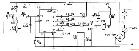
Control Circuit
Twinkling Ornamental Illuminations (2)
Published:2011/7/9 1:48:00 Author:Sue | Keyword: Twinkling, Ornamental, Illuminations | From:SeekIC

When IC2's Y1-Y3 terminals output high level(when one terminal outputs high level, other terminals will output low level), C4 will be charged. Its voltage will be put on VT's gate electrode through R6,NOT GATE D3,D4 and R8 which will make VT connected. HL will be illuminated. After VT is connected, C4 will charge VT through VD5. Because the resistance values of the resistor R3,R4,R5 are different from each other, when IC2's Y1-Y3 terminals output high level respectively, C4's charge time is different, which will make VT's conductingextents different. Then HL's working voltages are different which will make the illuminations brightness different. The smaller the resistor(R3-R5)'s resistance values are, the longer C4's charge time will be, the larger VT's conducting angle will be, the higher HL's working voltage will be, and the lighter the illuminations will be.
Reprinted Url Of This Article:
http://www.seekic.com/circuit_diagram/Control_Circuit/Twinkling_Ornamental_Illuminations_2.html
Print this Page | Comments | Reading(3)

Article Categories
power supply circuit
Amplifier Circuit
Basic Circuit
LED and Light Circuit
Sensor Circuit
Signal Processing
Electrical Equipment Circuit
Control Circuit
Remote Control Circuit
A/D-D/A Converter Circuit
Audio Circuit
Measuring and Test Circuit
Communication Circuit
Computer-Related Circuit
555 Circuit
Automotive Circuit
Repairing Circuit
Code: