Control Circuit
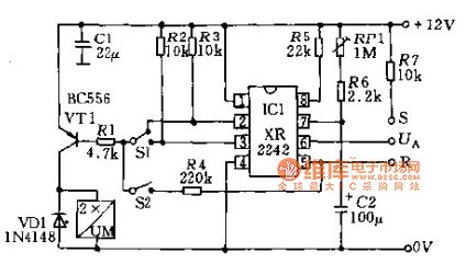
Timer switch circuit diagram
Published:2014/4/15 22:48:00 Author:lynne | Keyword: Timer switch circuit diagram, XR2242 | From:SeekIC

Monolithic circuit shown in FIG time transmitter circuit XR2242, timing time from a few milliseconds to a few days. The circuit comprises a time base oscillator, a binary counter 8 and a control trigger. Time base circuit by the resistor R and the capacitor C form, can have T = RC (pin 8). T = 2RC (pin 2) and T = 128RC (pin 3) three output pulse time by the applied voltage, the output can be reset automatically, use the flip-flop positive edge of the input pulse time can start the process. circuit output terminal (pin 6) voltage UA is low, so that the external action relays and other components. 6 may also be connected to the foot end of the R or S, the electric set or reset (switch S2 together). using the switch S1 can select the delay time. Timer switch circuit diagram shown in Figure:
Reprinted Url Of This Article:
http://www.seekic.com/circuit_diagram/Control_Circuit/Timer_switch_circuit_diagram.html
Print this Page | Comments | Reading(3)

Article Categories
power supply circuit
Amplifier Circuit
Basic Circuit
LED and Light Circuit
Sensor Circuit
Signal Processing
Electrical Equipment Circuit
Control Circuit
Remote Control Circuit
A/D-D/A Converter Circuit
Audio Circuit
Measuring and Test Circuit
Communication Circuit
Computer-Related Circuit
555 Circuit
Automotive Circuit
Repairing Circuit
Code: