Time Control
Voltage Regulator (the 5th)
Published:2011/7/3 5:07:00 Author:Felicity | Keyword: Voltage Regulator (the 5th) | From:SeekIC
Work of the circuit
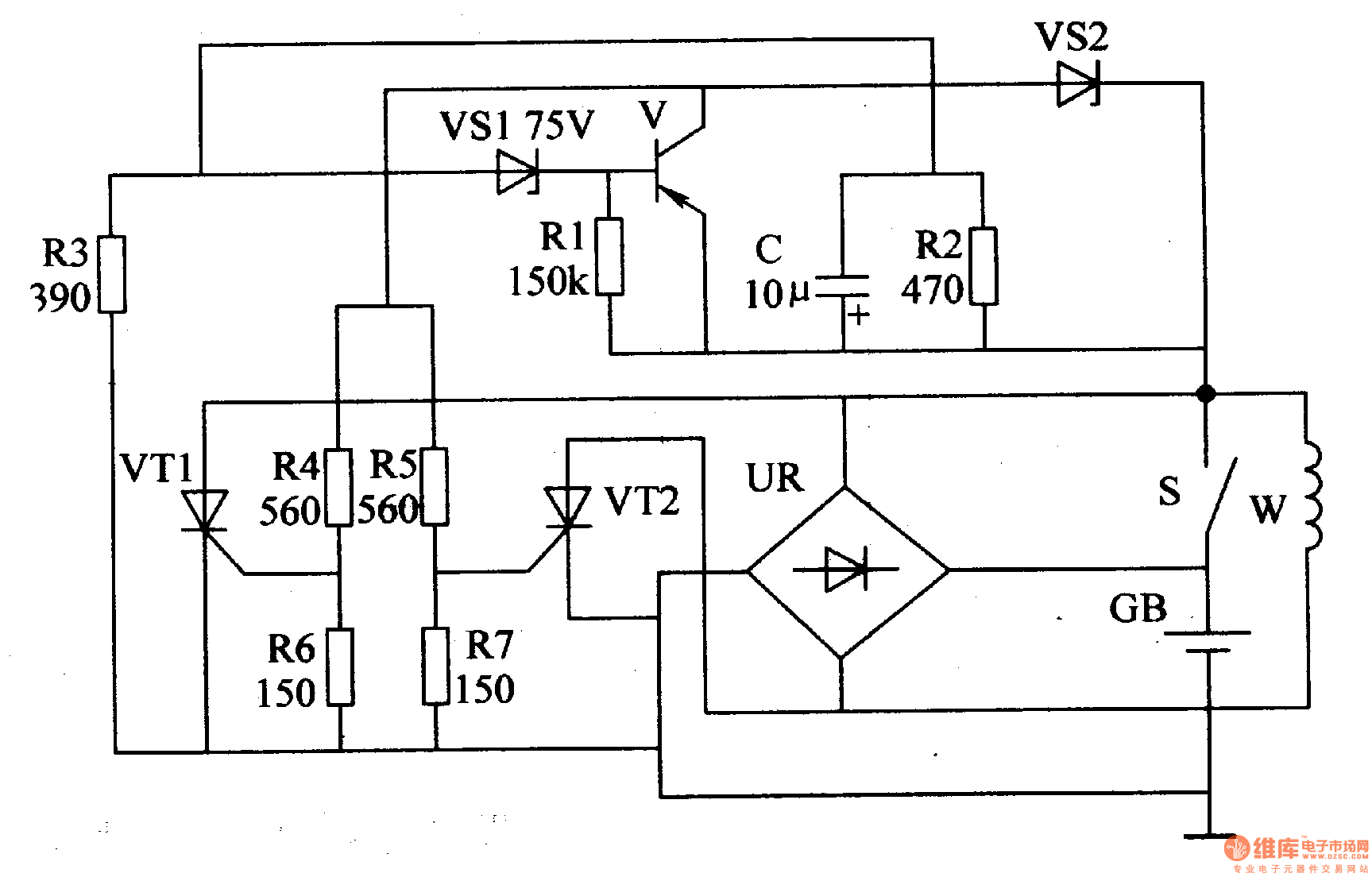
The circuit consists of time-based integrated circuit IC, potentiometer RP1, Rm, capacitor C1, C2, resistor R1-R5, stabilizing diode VS, diode VD and transistor V1 and V2. (It is showed in picture 7-144.)
When the motor van is working, the exporting voltage of W is rectified by UR. It then charges the battery TB and supplies power to the electrical equipment such as the light on the car. When the speed of the motor is low, the charging voltage on GB is lower than 14.5V. The exporting voltage is rectified by UR and then charges GB. When the speed of motor is high, the charging voltage on the GB is increasing. When the voltage is larger than 14.8V, the exporting current is shunted. In this way the charging voltage is stabilized to the value of 14.8V.
Reprinted Url Of This Article:
http://www.seekic.com/circuit_diagram/Control_Circuit/Time_Control/Voltage_Regulator_the_5th.html
Print this Page | Comments | Reading(3)

Article Categories
power supply circuit
Amplifier Circuit
Basic Circuit
LED and Light Circuit
Sensor Circuit
Signal Processing
Electrical Equipment Circuit
Control Circuit
Remote Control Circuit
A/D-D/A Converter Circuit
Audio Circuit
Measuring and Test Circuit
Communication Circuit
Computer-Related Circuit
555 Circuit
Automotive Circuit
Repairing Circuit
Code: