Time Control
SELF_RETRIGGERING_TIMED_ON_GENERATOR
Published:2009/6/22 22:47:00 Author:Jessie | From:SeekIC

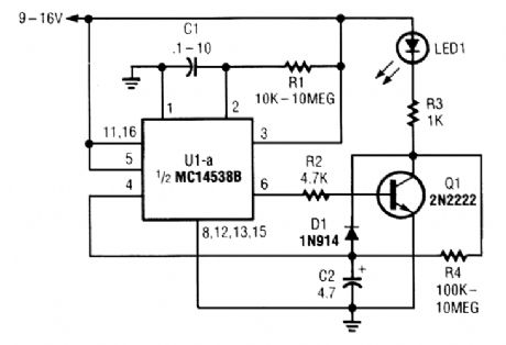
When power is first applied to the circuit, CZ begins to charge via LED1, R3, and R4. When the voltage across C2 reaches UI's input trigger level, the output of UI at pin 6 goes positive for a period that is determined by the values of C1 and R1. That turns Q1 on, discharging C2 through Dl and Q1.
At the end of the set period, the output of UI at pin 6 goes low, turning Q1 off and allowing the current to begin flowing through LED1, R3, and R4 to gain charge C2, causing the cycle to repeat.The repeat time is determined by the values of R3, R4, and C2. The previous formula won't be as accurate for this circuit, but it will at least get you close enough for the capacitor value; then R4, can be fine-tuned to obtain the desired timing period.
Reprinted Url Of This Article:
http://www.seekic.com/circuit_diagram/Control_Circuit/Time_Control/SELF_RETRIGGERING_TIMED_ON_GENERATOR.html
Print this Page | Comments | Reading(3)

Article Categories
power supply circuit
Amplifier Circuit
Basic Circuit
LED and Light Circuit
Sensor Circuit
Signal Processing
Electrical Equipment Circuit
Control Circuit
Remote Control Circuit
A/D-D/A Converter Circuit
Audio Circuit
Measuring and Test Circuit
Communication Circuit
Computer-Related Circuit
555 Circuit
Automotive Circuit
Repairing Circuit
Code: