Control Circuit
The precious electric appliance burglarproof alarm circuit
Published:2011/7/6 10:24:00 Author:qqtang | Keyword: electric appliance, burglarproof alarm | From:SeekIC

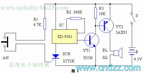
The circuit principle is shown in figure 1. SCR, R1 and AN can compose the SCR trigger switch circuit; IC1, R2, VT1, VT2 and BL compose the analog alarm whistle circuit. Usually, AN is pressed by the domestic appliance, both of its normally open contactors are disconnected, SCR is blocked without trigger signal, the alarm is not working. When the appliance is moved, the contactors of AN are closed, the trigger terminal of SCR is getting the signal from the positive pole of the power supply with the help of R1, SCR is conducting, IC1 is getting power and working, and the output terminal is outputting a police whistle signal which is amplified by VT1 and VT2.
Reprinted Url Of This Article:
http://www.seekic.com/circuit_diagram/Control_Circuit/The_precious_electric_appliance_burglarproof_alarm_circuit.html
Print this Page | Comments | Reading(3)

Article Categories
power supply circuit
Amplifier Circuit
Basic Circuit
LED and Light Circuit
Sensor Circuit
Signal Processing
Electrical Equipment Circuit
Control Circuit
Remote Control Circuit
A/D-D/A Converter Circuit
Audio Circuit
Measuring and Test Circuit
Communication Circuit
Computer-Related Circuit
555 Circuit
Automotive Circuit
Repairing Circuit
Code: