Control Circuit
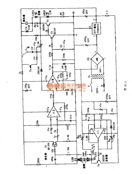
The long-distance alarm raster circuit
Published:2011/7/8 1:43:00 Author:Seven | Keyword: long-distance, alarm raster | From:SeekIC

The circuit consists of two parts, the emitter and receiver. The former consists of the computing amplifier 01, the capacitor C3 can be rectified to 1kHz, the potentiometer Rpz regulates the width of the pulse ultra-sonic wave, the potentiometer Rp1 limits the emitting current in a certain range. The input terminal of the receiver is the LDR or the optical transistor. The pulse light is converted into the AC current, the computing amplifier 0II is controlled by the FET T1, and its output controls the amplifier 0III. To allow it to receive signals in bad or remote environments, the signal from the 0III needs to by magnified by T2 and T3.
Reprinted Url Of This Article:
http://www.seekic.com/circuit_diagram/Control_Circuit/The_long_distance_alarm_raster_circuit.html
Print this Page | Comments | Reading(3)

Article Categories
power supply circuit
Amplifier Circuit
Basic Circuit
LED and Light Circuit
Sensor Circuit
Signal Processing
Electrical Equipment Circuit
Control Circuit
Remote Control Circuit
A/D-D/A Converter Circuit
Audio Circuit
Measuring and Test Circuit
Communication Circuit
Computer-Related Circuit
555 Circuit
Automotive Circuit
Repairing Circuit
Code: