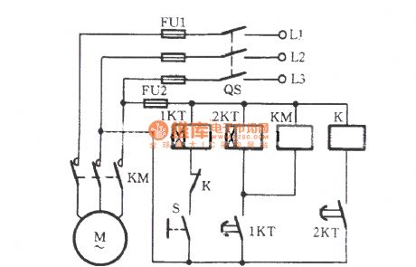
Control Circuit
The interval operational circuit of starting time delay
Published:2011/7/5 20:12:00 Author:Borg | Keyword: operational circuit, time delay | From:SeekIC

Working process: the power supply switch of QS is closed first, then the hand switch S is closed. At this moment, M is not starting immediately, but the relay 1KT is getting power and the timing is starting, when it is the regulated time of 1KT, its delaying contactor is closing, when the time relay coil of 2KT gets power and is starting to time, the coil of the AC contactor KM is getting power, the main contactor of KM is taking action, M is starting. After some time, the contactor of 2KT is taking action, the relay K is pulling in, and the normally open contactor is cut off.
Reprinted Url Of This Article:
http://www.seekic.com/circuit_diagram/Control_Circuit/The_interval_operational_circuit_of_starting_time_delay.html
Print this Page | Comments | Reading(3)

Article Categories
power supply circuit
Amplifier Circuit
Basic Circuit
LED and Light Circuit
Sensor Circuit
Signal Processing
Electrical Equipment Circuit
Control Circuit
Remote Control Circuit
A/D-D/A Converter Circuit
Audio Circuit
Measuring and Test Circuit
Communication Circuit
Computer-Related Circuit
555 Circuit
Automotive Circuit
Repairing Circuit
Code: