Control Circuit
The auto reset over-voltage protection circuit
Published:2011/7/5 21:24:00 Author:Borg | Keyword: auto reset, over-voltage protection | From:SeekIC
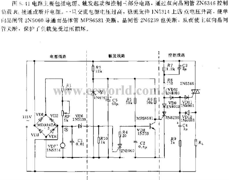
The circuit in figure 5.41 includes the power supply, trigger starting and control circuit, it controls ON/OFF of the load R1 with the help of the dual-way thyristor ZN6346. Once the AC power supply voltage is too high, the voltage on point A of the stable element LN5314 will be rising up, which makes the single-way thyristor 2N5060 conducting and transistor MPS6581 break down, so is the thyristor 2N6239, so the main dual-way thyristor is broken down, the load is protected from being broken due to over-voltage.
Reprinted Url Of This Article:
http://www.seekic.com/circuit_diagram/Control_Circuit/The_auto_reset_over_voltage_protection_circuit.html
Print this Page | Comments | Reading(3)

Article Categories
power supply circuit
Amplifier Circuit
Basic Circuit
LED and Light Circuit
Sensor Circuit
Signal Processing
Electrical Equipment Circuit
Control Circuit
Remote Control Circuit
A/D-D/A Converter Circuit
Audio Circuit
Measuring and Test Circuit
Communication Circuit
Computer-Related Circuit
555 Circuit
Automotive Circuit
Repairing Circuit
Code: