Control Circuit
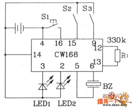
The CW168 new flash alarm integrated circuit
Published:2011/6/30 4:40:00 Author:Seven | Keyword: flash alarm, integrated circuit | From:SeekIC

R1 is the external oscillating circuit of the internal oscillator, by changing the resistance of R1, the oscillating frequency of the oscillator inside IC can be changed, when R1=330kΩ, the IC is outputting the 4Hz flashing frequency, and the IC stops working in 16s after it is triggered for a single time. To strength the sound effect, a power triode can be connected with the output terminal, which makes the output drive the loudspeaker. Besides, it can also be connected with all kinds of control circuits to trigger CW168, so the self-control is fulfilled.
Reprinted Url Of This Article:
http://www.seekic.com/circuit_diagram/Control_Circuit/The_CW168_new_flash_alarm_integrated_circuit.html
Print this Page | Comments | Reading(3)

Article Categories
power supply circuit
Amplifier Circuit
Basic Circuit
LED and Light Circuit
Sensor Circuit
Signal Processing
Electrical Equipment Circuit
Control Circuit
Remote Control Circuit
A/D-D/A Converter Circuit
Audio Circuit
Measuring and Test Circuit
Communication Circuit
Computer-Related Circuit
555 Circuit
Automotive Circuit
Repairing Circuit
Code: