Control Circuit
Telephone burglar alarm circuit
Published:2011/7/9 9:53:00 Author:Fiona | Keyword: burglar alarm | From:SeekIC

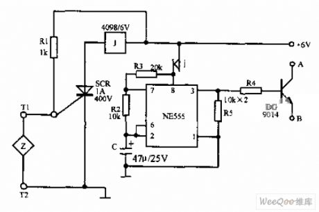
Telephone burglar alarm circuit is shown as above,it is formed by the SCR,relay,NE555 and peripheral components. When the sensor Z is connected, the whole machine is in waiting state,the circuit works. A, B are respectively connected to telephone handfree knob which is stored at pulse dial-up and has the hands free function and the joint of the storage number keys.When the sensor Z is off due to happen stolen situation,the circuit works,A and B are connected,it is equal to off-hook and sending out the storage alarm number (such as 110 or your local phone number).
Reprinted Url Of This Article:
http://www.seekic.com/circuit_diagram/Control_Circuit/Telephone_burglar_alarm_circuit.html
Print this Page | Comments | Reading(3)

Article Categories
power supply circuit
Amplifier Circuit
Basic Circuit
LED and Light Circuit
Sensor Circuit
Signal Processing
Electrical Equipment Circuit
Control Circuit
Remote Control Circuit
A/D-D/A Converter Circuit
Audio Circuit
Measuring and Test Circuit
Communication Circuit
Computer-Related Circuit
555 Circuit
Automotive Circuit
Repairing Circuit
Code: