Control Circuit
TELEPHONE_OPERATED_ac_POWER_SWITCH
Published:2009/7/10 21:35:00 Author:May | From:SeekIC
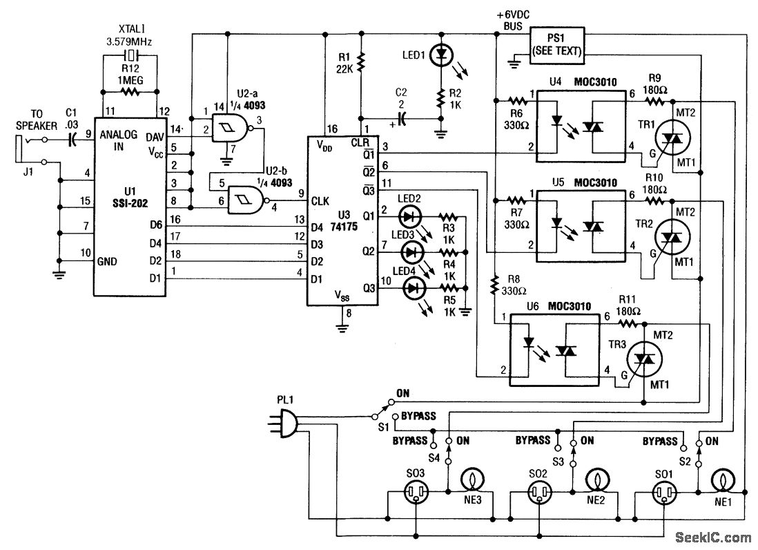
Tones (from the DTMF) on the telephone line are detected by U1. When a valid tone is received, pin 14 (D/V) of U1 produces a positive pulse that is used to drive NAND gates U2A and U2B and then to latch binary data from U1 into Quad-D flip-flop U3 (U1 could be decoded into 16 bits, if required). The Q outputs of U3 drive optoisolators that control triacs TR1, TR2, and TR3. PS1 is a 6-V 150-mA dc adapter that operates from 120 Vac.
Reprinted Url Of This Article:
http://www.seekic.com/circuit_diagram/Control_Circuit/TELEPHONE_OPERATED_ac_POWER_SWITCH.html
Print this Page | Comments | Reading(3)

Article Categories
power supply circuit
Amplifier Circuit
Basic Circuit
LED and Light Circuit
Sensor Circuit
Signal Processing
Electrical Equipment Circuit
Control Circuit
Remote Control Circuit
A/D-D/A Converter Circuit
Audio Circuit
Measuring and Test Circuit
Communication Circuit
Computer-Related Circuit
555 Circuit
Automotive Circuit
Repairing Circuit
Code: