Switch Control
Ultrasonic remote light switch circuit diagram
Published:2011/8/9 18:03:00 Author:Vicky | Keyword: ultrasonic, remote light switch | From:SeekIC

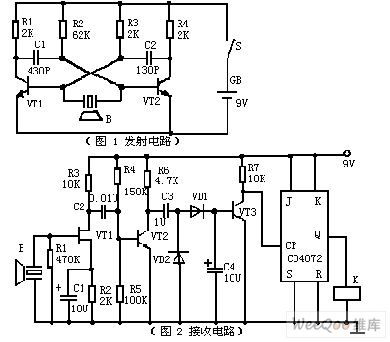
Picture 1 is a emitter circuit. The circuit uses discrete devices. VT1, VT1, R1, R2, R3, R4 , C1 and C2 constitute a self-excitation multivibrator. Ultrasonic emitting device B is connected in the collector loop of VT1 and VT2 to conduct push-pull work. The time of loop is often determined by R1, C1, R4 and C2. The resonance frequency of ultrasonic receptor device B triggers the multivibrator circuit. Hence, the circuit can work under optimized frequency.
Picture 2 is a receiving circuit, JFET VT1 constitutes high-input resistance amplifier, which performs better working with ultrasonic receptor device B and obtains higher receiving sensitiveness and better frequency-selecting performance.
Reprinted Url Of This Article:
http://www.seekic.com/circuit_diagram/Control_Circuit/Switch_Control/Ultrasonic_remote_light_switch_circuit_diagram.html
Print this Page | Comments | Reading(3)

Article Categories
power supply circuit
Amplifier Circuit
Basic Circuit
LED and Light Circuit
Sensor Circuit
Signal Processing
Electrical Equipment Circuit
Control Circuit
Remote Control Circuit
A/D-D/A Converter Circuit
Audio Circuit
Measuring and Test Circuit
Communication Circuit
Computer-Related Circuit
555 Circuit
Automotive Circuit
Repairing Circuit
Code: