Switch Control
SOUND_ACTIVATED_TAPE_SWITCH
Published:2009/7/7 20:38:00 Author:May | From:SeekIC

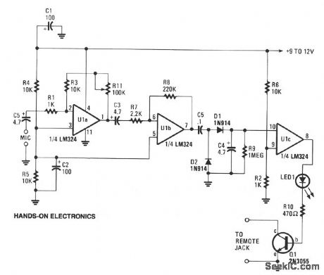
This circuit can cause a cassette recorder to automatically turn on and record when a sound or noise is present. Another use, is when the sound-activated switch is used to turn on a cassette player so that it operates as a burglar-alarm detector and sounder. Op amps U1a and U1b are connected in tandem to amplify the sounds picked up by the detector's mike. The amplified audio voltage, output at pin 7 of U1b, is fed to a voltage-doubler circuit, consisting of D1 and D2. The elevated voltage from the doubler circuit is input to the positive input of op amp U1c, which is operating as a simple comparator circuit. The other input of Ulc is connected to a voltage divider that sets the switching point for the dc signal voltage, to turn on when the signal level is greater than about 1.5 V. As the comparator switches on, its output at pin 8 becomes positive and supplies a forward bias to turn on D3 and Q1, which in turn, starts the recorder. The rc combination of C4/R9 sets the cassette's run time after the input sound has ceased, preventing the recorder from chopping-up or turning-off between closely spaced sounds or words picked up by the mike. The delay time is roughly 6 to 8 seconds. R11 sets the circuit's gain. Connect a low-impedance cassette mike to the amplifier's input, and connect the output of Q1 to the cassette's remote input or to the internal input and set the recorder to the record position. Talk and adjust the amplifier's gain with R11 for the desired sensitivity.
Reprinted Url Of This Article:
http://www.seekic.com/circuit_diagram/Control_Circuit/Switch_Control/SOUND_ACTIVATED_TAPE_SWITCH.html
Print this Page | Comments | Reading(3)

Article Categories
power supply circuit
Amplifier Circuit
Basic Circuit
LED and Light Circuit
Sensor Circuit
Signal Processing
Electrical Equipment Circuit
Control Circuit
Remote Control Circuit
A/D-D/A Converter Circuit
Audio Circuit
Measuring and Test Circuit
Communication Circuit
Computer-Related Circuit
555 Circuit
Automotive Circuit
Repairing Circuit
Code: