Switch Control
HIGH_PERFORMANCE_VIDEO_SWITCH
Published:2009/7/9 3:09:00 Author:May | From:SeekIC

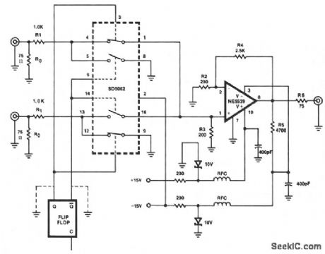
This figure shows a one-of-two switch with a summing amplifier. The video source's line can be termi-nated either externally or internally to switch R0. With this termination resistor, a load change of less than 1 Ω will be seen by the source when the switch changes state. For this reason, input isolation amplifiers are not necessary. R4 can be varied to control circuit gain, but should never be less than 1400 Ω since the NE5539 is internally compensated for gain values greater than seven. A value of approximately 2500 Ω for R4 will set circuit gain to near unity. Additionally, the circuit output impedance is set by R6, and R5 sets the output dc offset to near zero.
Reprinted Url Of This Article:
http://www.seekic.com/circuit_diagram/Control_Circuit/Switch_Control/HIGH_PERFORMANCE_VIDEO_SWITCH.html
Print this Page | Comments | Reading(3)

Article Categories
power supply circuit
Amplifier Circuit
Basic Circuit
LED and Light Circuit
Sensor Circuit
Signal Processing
Electrical Equipment Circuit
Control Circuit
Remote Control Circuit
A/D-D/A Converter Circuit
Audio Circuit
Measuring and Test Circuit
Communication Circuit
Computer-Related Circuit
555 Circuit
Automotive Circuit
Repairing Circuit
Code: