Switch Control
HALL_EFFECT_SWITCHES
Published:2009/7/7 7:31:00 Author:May | From:SeekIC

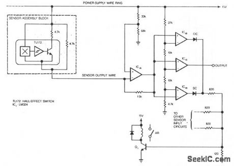
Hall-effect switches have several advantages over mechanical and optically coupled switches. They're insensitive to environmental light and dirt, they don't bind, and they don't sustain mechanical wear. Their major drawback is that they require three wires per device. The circuit shown, however, reduces this wire count to N + 1 wires for N devices.Amplifier IC1A is configured as a current-to-voltage converter. It senses the sensor assembly's out-put current. When the Hall-effect switch is actuated, the sensor's output current increases to twice its quiescent value. Amplifier IC1B, configured as a comparator, detects this increase. The comparator's out-put decreases when the Hall-effect switch turns on.The circuit also contains a fault-detection function. If any sensor output wire is open, its correspond-ing LED will turn on. If the power-supply line opens, several LEDs will turn on. A short circuit will also turn an LED on. Every time an LED turns on, Q1 turns on and the alarm relay is actuated.
Reprinted Url Of This Article:
http://www.seekic.com/circuit_diagram/Control_Circuit/Switch_Control/HALL_EFFECT_SWITCHES.html
Print this Page | Comments | Reading(3)

Article Categories
power supply circuit
Amplifier Circuit
Basic Circuit
LED and Light Circuit
Sensor Circuit
Signal Processing
Electrical Equipment Circuit
Control Circuit
Remote Control Circuit
A/D-D/A Converter Circuit
Audio Circuit
Measuring and Test Circuit
Communication Circuit
Computer-Related Circuit
555 Circuit
Automotive Circuit
Repairing Circuit
Code: