Switch Control
AUTOMATIC_VIDEO_SWlTCH
Published:2009/7/9 3:06:00 Author:May | From:SeekIC

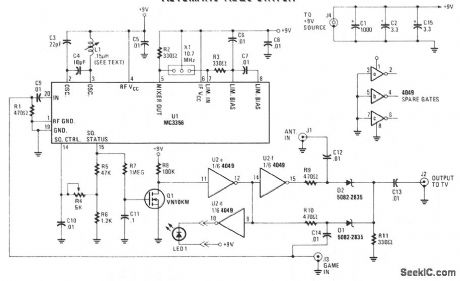
Turn on a game, computer, videodisc player, or whatever, and its output takes priority over the antenna-derived signal-the antenna is disconnected and the alternate source is fed to the monitor. When the alternate video source is no longer detected, the switch automatically reconnects the antenna. When the rf carrier is detected, a high logic output appears at pin 15 of U1-squelch status. The signal is then buffered to VMOS FET Q1. This FET can drive CMOS inverter/buffer U2, can be an open-drain output to drive a relay, or can convert to a 5 V logic level. When pin 15 of U1 becomes high, Q1 turns on, pulling pin 11 of U2e low; in turn, pin 12 becomes high. The output of U2e is fed to U2f, forcing its output, at pin 15, low. When the signal at U2 pin 12 is high, D1 is biased on, allowing the signal at J3 to flow through C14, D1, and out to J2 through C13. When the signal at J3 is removed, U1 pin 15 decreases. That decrease causes U2 pin 12 to decrease and U2 pin 15 to increase. When the signal at U2 pin 15 is high, it biases D2 on, allowing the signals at J1 to flow through C12, D2, and out to J2 through C13.
Reprinted Url Of This Article:
http://www.seekic.com/circuit_diagram/Control_Circuit/Switch_Control/AUTOMATIC_VIDEO_SWlTCH.html
Print this Page | Comments | Reading(3)

Article Categories
power supply circuit
Amplifier Circuit
Basic Circuit
LED and Light Circuit
Sensor Circuit
Signal Processing
Electrical Equipment Circuit
Control Circuit
Remote Control Circuit
A/D-D/A Converter Circuit
Audio Circuit
Measuring and Test Circuit
Communication Circuit
Computer-Related Circuit
555 Circuit
Automotive Circuit
Repairing Circuit
Code: